
An optical element anisotropy detection device

An optical element and anisotropy technology, applied in the field of optical element anisotropy detection device, can solve the problems of inability to detect the anisotropy of optical elements, inability to accurately measure optical elements, etc., to eliminate measurement blind spots, reduce mode competition, less demanding effects

Active Publication Date: 2014-10-22
TSINGHUA UNIV
View PDF5 Cites 0 Cited by
  • Summary
  • Abstract
  • Description
  • Claims
  • Application Information

AI Technical Summary

Problems solved by technology

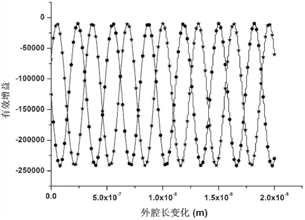
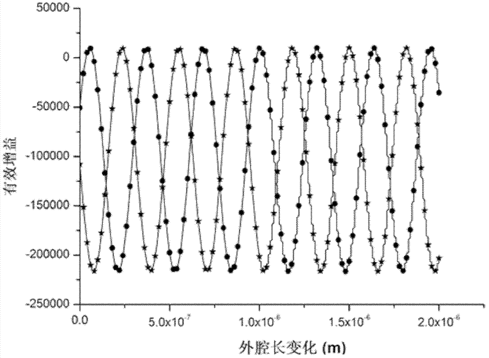
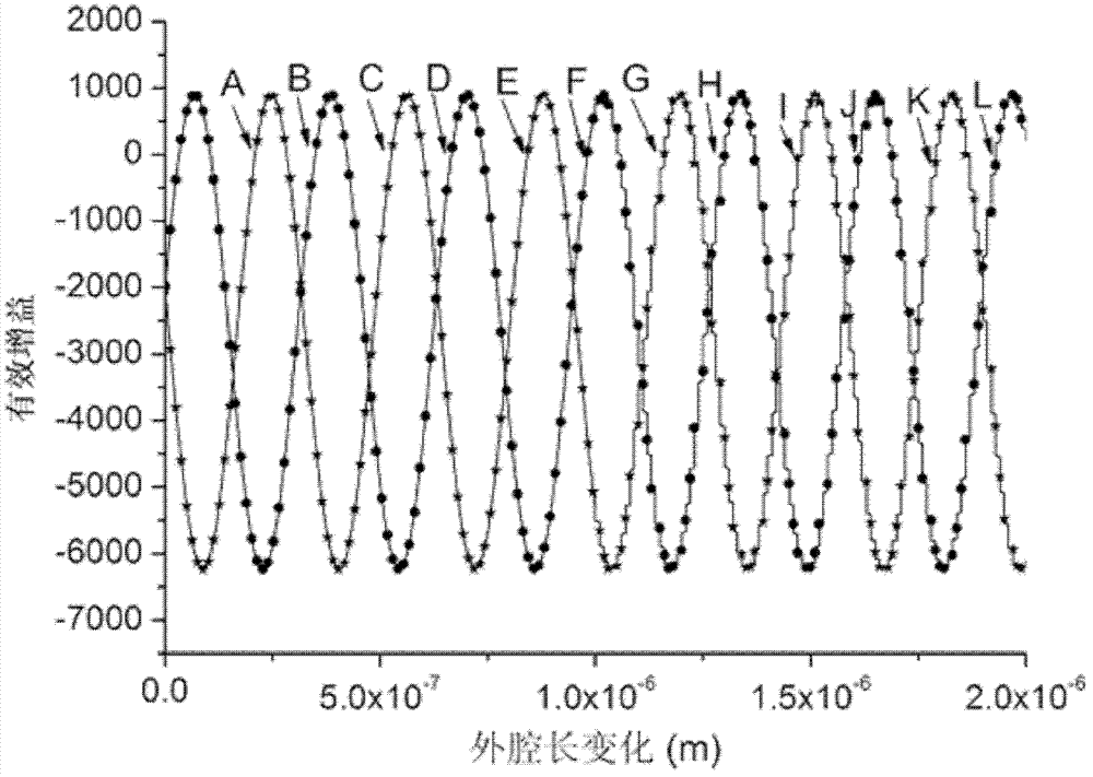
However, due to the mode competition inside the laser, if the anisotropy of the optical element to be measured is very small when placed in the feedback external cavity, the polarization state of the laser will not jump when the cavity length of the feedback external cavity is changed, that is, the optical element The anisotropy of the optical element cannot be detected, so there is a measurement blind zone in the laser feedback measurement method. After testing, it is found that the measurement blind zone is two intervals of phase delay 0°~15° and 165°~180°. When the anisotropy of the optical element is in the measurement blind zone , the laser feedback measurement method cannot accurately measure the anisotropy of this optical element

Method used


Image

  • An optical element anisotropy detection device
  • An optical element anisotropy detection device
  • An optical element anisotropy detection device

Examples


Embodiment Construction

[0017] The present invention will be described in detail below in conjunction with the accompanying drawings and embodiments.

[0018] If an anisotropic optical element is placed in the laser resonator, the laser light emitted by the laser can be split into two beams of light with two eigenmode polarization directions perpendicular to each other. These two kinds of light are usually represented by o light and e light . In the semiclassical theory of lasers, whether the laser mode can oscillate depends on two conditions:

[0019] alpha o >0, α e >0

[0020] α ′ o = α o - α e θ oe β e > 0 , α ′ e = α ...


PUM


Abstract

The invention relates to a detection device for anisotropy of an optical element, and the detection device comprises a laser device, a feedback outer cavity, a signal control system and a signal processing system, wherein the laser device comprises a laser gain tube, the left side of the axis of the laser gain tube is provided with an inner cavity concave-surface reflecting mirror, the right side of the axis of the laser gain tube is sequentially provided with an anti-reflection window and an outer cavity planar reflecting mirror, and the outer cavity planar reflecting mirror and a feedback mirror arranged at the right side of the outer cavity planar reflecting mirror form the feedback outer cavity. The detection device provided by the invention is characterized in that the device also comprises a force applying element, wherein the radial direction of the force applying element is provided with more than one threaded hole, and the force applying element passes through the threaded holes through screws to be propped against on the anti-reflection window. The detection device provided by the invention can be widely applied in the detection to the anisotropy of the optical element by a laser feedback measurement method.

Description

technical field [0001] The invention relates to a device for detecting parameters of an optical element, in particular to a device for detecting anisotropy of an optical element. Background technique [0002] The anisotropy of optical components includes the anisotropy formed by natural birefringent materials or artificial birefringent materials, such as the phase retardation of wave plates, and also includes the stress birefringence of isotropic optical components due to the residual stress introduced during processing. Among them, the measurement accuracy of the phase delay of the wave plate directly affects the accuracy of the entire system, and the residual stress inside the optical component has an important impact on the imaging quality and aberration of the optical system. Therefore, it is of great significance to accurately measure the anisotropy of optical components. In the prior art, the detection of the anisotropy of the optical element is usually represented by...

Claims


Application Information

Patent Timeline
Patent Type & Authority Patents(China)
IPC IPC(8): G01M11/02
Inventor 张书练陈文学
Owner TSINGHUA UNIV
Learn More