Multi-fractal heatsink system and method

a heat sink and multi-fractal technology, applied in the direction of lighting, heating apparatus, instruments, etc., can solve the problems of insufficient cooling, poor heat loss efficiency, and the possibility of diminishing the return of larger heat sinks, etc., to achieve low noise, facilitate heat exchange, and reduce the effect of heat loss

Active Publication Date: 2019-01-17
FRACTAL HEATSINK TECH
View PDF0 Cites 22 Cited by
  • Summary
  • Abstract
  • Description
  • Claims
  • Application Information

AI Technical Summary

Benefits of technology

[0055]For example, in a computer system, a power supply with a fan may be located near the heat sink. It will therefore create an environmental asymmetry, to which the design of the heat sink may respond. Likewise, the heat sink may be within a physical enclosure, and may have an asymmetric ventilation path, all leading to an asymmetric optimized design for the external heat sink shape and characteristics. Further, the branching itself may be asymmetric, such that a larger portion of the heat flow is transmitted down a larger branch, while a smaller portion is transmitted down a narrower branch. However, due to geometry, the ratio of surface area (˜2πr) to cross section area (˜πr2)≈(2 / r) is smaller for the larger branch than the smaller one, leading to a greater heat dissipation efficiency for the smaller branch, just distal to the branching point, than the larger branch. Meanwhile, the larger branch more efficiently carries the heat load away from the branching point, and thus reduces competition for convective heat loss near the branching point with respect to a narrower branch. Therefore, a fractal design, with asymmetric branching, can optimize the heat dissipation of the heat sink over space. Further, because the branching may be defined algorithmically, the various environmental and spatial factors may all play a role in an iterative optimized design, herein referred to as a fractal heat sink.
[0228]It is a still further object to provide a method of dissipating heat, comprising: providing a heat transmissive body, having a base configured to receive a heat load, and a three dimensional configuration having an external surface configured to transfer a heat load corresponding to the heat load received by the base to an external heat transfer fluid; interacting a multiscale pattern associated with the external surface with a flow of the external heat transfer fluid, to generate turbulence in the a flow of the external heat transfer fluid and reduce a stagnant surface layer to facilitate heat transfer; and controlling the flow of the external heat transfer fluid based on at least one measurement corresponding to at least one of a heat transfer of the heat load to the external heat transfer fluid and a turbulence of the flow of the external heat transfer fluid. The controlling may be dependent on an acoustic emission, a correspondence of a temperature of the heat transmissive body to a computation flow dynamics model of heat transfer in the heat transmissive body, a thermodynamic parameter. The control can alter turbulence, and in particular may control the onset or occurrence of significant turbulence, the location of turbulence, and amount of turbulence, for example. On the other hand, the control can seek to avoid turbulence, and modify flow parameters to meet thermal criteria while avoiding objectionable noise. The control can also dynamically change turbulence, for example as a way to create concentrated surface forces as a way to dislodge particles on the surface of the heat sink. Further, by dynamically controlling turbulence, heat dissipation may be selectively increased in various regions of the heat sink at different times. The dynamic process may therefore locally reduce air flow to permit an increase in temperature, and then selectively increase the air flow, providing high efficiency heat dissipation due to the combination of higher temperature differential and reduced boundary layer thickness. This dynamic process may have a higher efficiency than a static process wherein the temperature differential between the heat sink surface and the heat transfer medium is stabilized at a low difference, and a uniform, distributed air flow leads to a uniformly relatively thicker boundary layer.

Problems solved by technology

This leads to a possibility of diminishing return on larger heat sinks, since the radiative and convective dissipation tends to be related to the temperature differential between the heat sink surface and the external medium.
Therefore, if the heat sink is oversized, the efficiency of heat shedding is poor.
If the heat sink is undersized, the object may be insufficiently cooled, the surface of the heat sink dangerously hot, and the heat shedding not much greater than the object itself absent the heat sink.
The result is significant loss of heat sink efficiency.
The above equations show that when the airflow through or around the heat sink decreases, this results in an increase in the average air temperature.
This in turn increases the heat sink base temperature.
Therefore, if there is no air or fluid flow around the heat sink, the energy dissipated to the air cannot be transferred to the ambient air.
Therefore, the heat sink functions poorly.
If a heat sink is initially optimized, the accretion of dust at the surface will de-optimize the air flows and heat conductivity of heat sink fins, and also decrease efficiency on that basis.
Dust accumulation can increase local turbulence, and in turbulent flow zones, the dust accumulation may not be uniform.
A heat sink may have impaired efficiency when: (a) pin fins have a lot of surface area, but the pins are so close together that air has a hard time flowing through them; (b) aligning a heat sink so that the fins are not in the direction of flow; (c) aligning the fins horizontally for a natural convection heat sink.
However, it is not recommended for machining, since it is a relatively soft material.
Copper is also around four to six times more expensive than aluminum, but this is market dependent.
Diamond is another possible heat sink material, typically limited in use by cost and fabrication issues.
In a heat sink, this means that heat does not distribute uniformly through the heat sink base.
This non-uniformity increases the heat sink's effective thermal resistance.
However, this is not always true, since the actual heat dissipation is influenced by thermal gradients and convective flow, each of which is independent of surface area per se.
(Because of convective flow, orientation with respect to the gravitational vector is often an issue in heat sinks).
A layer of coating on the heat sink can then be counterproductive, as its thermal resistance can impair heat flow from the fins to the coolant.
Finned heat sinks with convective or forced flow will not benefit significantly from being colored.
However, larger surface flow velocities will increase the heat transfer efficiency, especially where the flow near the surface is turbulent, and substantially disrupts a stagnant surface boundary layer.
Primore notes that the design suffers if there is laminar flow (which creates a re-circulation region in the fluid outlet, thereby completely eliminating the benefit of the chimney) but benefits if there is turbulent flow which allows heat to travel from the parallel plates into the chimney and surrounding fluid.
In many cases, the heat sink operates in a non-ideal environment subject to dust or oil; therefore, the heat sink design must accommodate the typical operating conditions, in addition to the as-manufactured state.
Even in passive dissipative device, convective flow may be a significant factor, and reducing air flow volume and velocity by increasing the effective impedance can be counterproductive.
On the other hand, in some cases, the amount of energy necessary to move the air is dwarfed by the problem to be solved.
In many computing systems, the processors are thermally constrained, that is, the functioning of the processor is limited by the ability to shed heat.
Indeed, while typically, the most efficient cooling will result from directing the air flow toward a hot spot, this is not necessarily the case, since the air flow effects are no-linear and interactive with other parameters.

Method used


Image

  • Multi-fractal heatsink system and method
  • Multi-fractal heatsink system and method
  • Multi-fractal heatsink system and method

Examples


Embodiment Construction

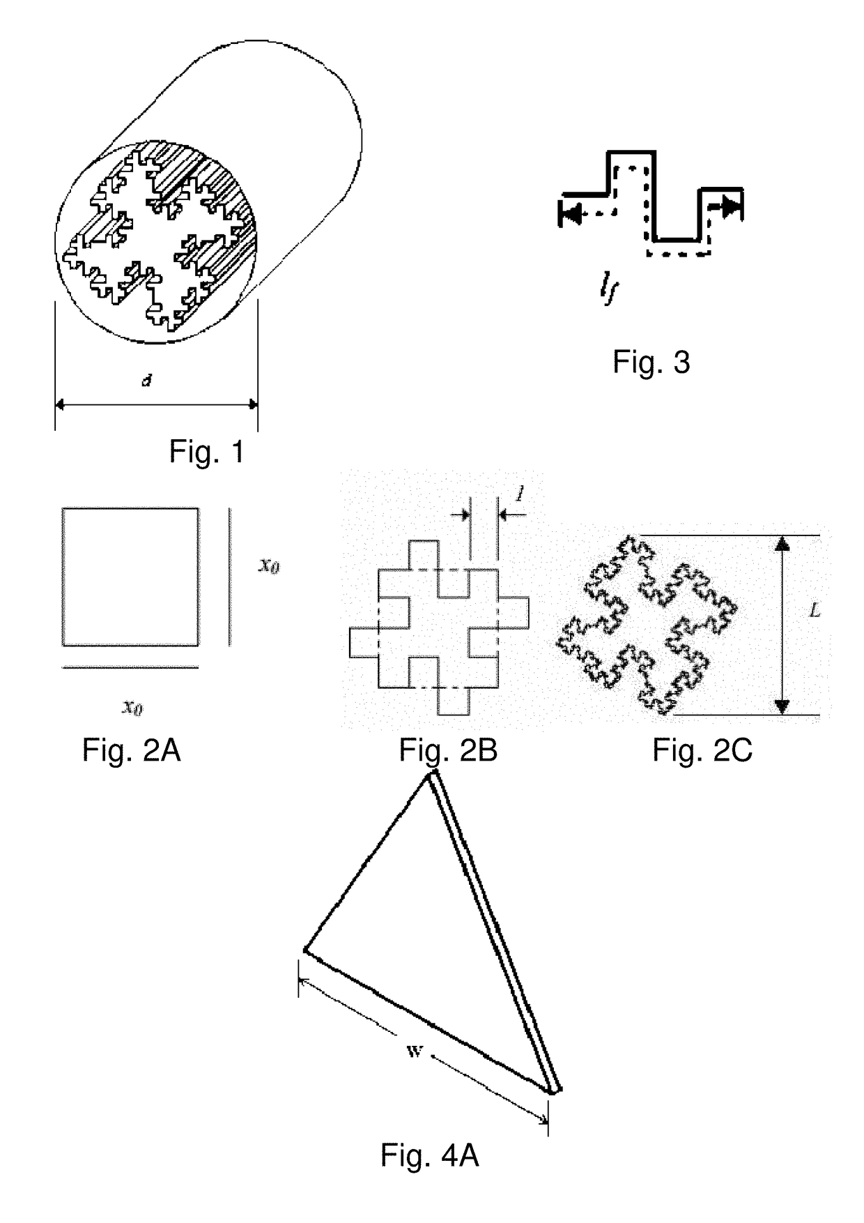
[0258]FIG. 1 illustrates a fractal heat sink that is an exemplary embodiment of the invention. In this embodiment, the heat sink is based on a Quadratic Koch Island. In a shorter length, this also represents a fractal flow filter. The Quadratic Koch Island may have a regular or irregular twist pattern within the shroud. FIG. 2A illustrates the basis for the Quadratic Koch Island. FIG. 2B illustrates a Quadratic Koch Island obtained after application of one iteration. FIG. 2C illustrates a Quadratic Koch Island obtained after application of several iterations. FIG. 3 illustrates the total length of all the fractal segments of a Quadratic Koch Island.

[0259]FIG. 2A illustrates a square with dimension x0 that forms the basis for the Quadratic Koch Island. FIG. 2B illustrates a Quadratic Koch Island obtained after application of one fractal iteration on the square. The fractal with section lengths of l is applied to each side of the square in the first iteration. Similarly, after several...


PUM


Abstract

A heat sink comprising a heat exchange device having a large scale morphology over a scale range and a small scale texture over a scale range, wherein at least one of the large scale morphology and the small scale texture has a fractal-like self-similarity over a scale range. The large scale morphology and small scale texture may be independently defined and implemented, or be provided with a transitional range. The large scale morphology may be algorithmically optimized according to a set of geometrically constraints. The small scale texture may be optimized according to aerodynamic parameters and constraints. The heat sink may be dynamically varying, and / or operated in conjunction with a dynamically varying heat transfer medium supply.

Description

CROSS REFERENCE TO RELATED APPLICATIONS[0001]The present application claims benefit of priority from U.S. Provisional Patent Application Ser. No. 62 / 533,421, filed Jul. 17, 2017, the entirety of which is expressly incorporated herein by reference. This application is also related to U.S. Patent Application No. 61 / 331,103, filed May 4, 2010, Ser. No. 13 / 106,640, filed May 12, 2011, Ser. No. 14 / 817,962, filed Aug. 4, 2015, Ser. No. 14 / 984,756, filed Dec. 30, 2015, Ser. No. 15 / 205,906, filed Jul. 8, 2016, 62 / 361,253, filed Jul. 12, 2016, and Ser. No. 15 / 648,065, filed Jul. 12, 2017, each of which is expressly incorporated herein by reference in its entirety.FIELD OF THE INVENTION[0002]This invention relates to the field of heat sinks or devices that transfer heat between a heat source and a fluid, and more particularly to heat sink designs exploiting fractal geometry principles.BACKGROUND OF THE INVENTION[0003]All references cited herein are expressly incorporated by reference in their...

Claims


Application Information

Patent Timeline
Patent Type & Authority Applications(United States)
IPC IPC(8): H05K7/20F28F13/12H01L23/467H01L23/473G05B15/02
CPCH05K7/20154F28F13/12H05K7/20281H01L23/467G05B15/02H05K7/20209H05K7/20272H05K7/20172H01L23/473H01L23/367H01L23/3736H01L21/4871F28F2210/02F28F2215/10F28F3/048H05K7/20136H05K7/20418
Inventor POLTORAK, ALEXANDER
Owner FRACTAL HEATSINK TECH
Why Eureka
Try Eureka