Check patentability & draft patents in minutes with Patsnap Eureka AI!

Intelligent reactive compensation device based on single three-pole synchronous switch

A technology of synchronous switch and compensation device, which is applied in the fields of harmonic filtering, grid power quality control, and reactive power compensation. It can solve problems such as unbalanced capacitor banks, different DC potentials at stop, and complex drive timing, etc., to achieve excellent performance. Electrical switching effect, the effect of the best electrical performance

Active Publication Date: 2012-07-25
北京馨容纵横科技发展有限公司
View PDF12 Cites 12 Cited by
  • Summary
  • Abstract
  • Description
  • Claims
  • Application Information

AI Technical Summary

Problems solved by technology

The structure of three unipolar synchronous switches is more complicated than that of a single three-pole synchronous switch, and there are more driving circuits, and each unipolar switch requires an independent switch coil and driving circuit, and the driving sequence is complicated
However, the zero potential of the three-phase circuit of this circuit topology is prone to drift, and the DC potential of the capacitors in each phase of the capacitor bank is different, and it may be very high when it is abnormal, just like the phenomenon of voltage doubler rectification, which will affect the three-pole synchronization The potential of the main contact of the switch is not conducive to the safe operation of the system
Moreover, when the capacitor bank is in an unbalanced state, the sum of the currents of the three main contacts of the synchronous switch is still equal to zero according to Kirchhoff's current law, and it is not easy to observe the unbalanced situation of the capacitor bank

Method used


Image

  • Intelligent reactive compensation device based on single three-pole synchronous switch
  • Intelligent reactive compensation device based on single three-pole synchronous switch
  • Intelligent reactive compensation device based on single three-pole synchronous switch

Examples


Embodiment Construction

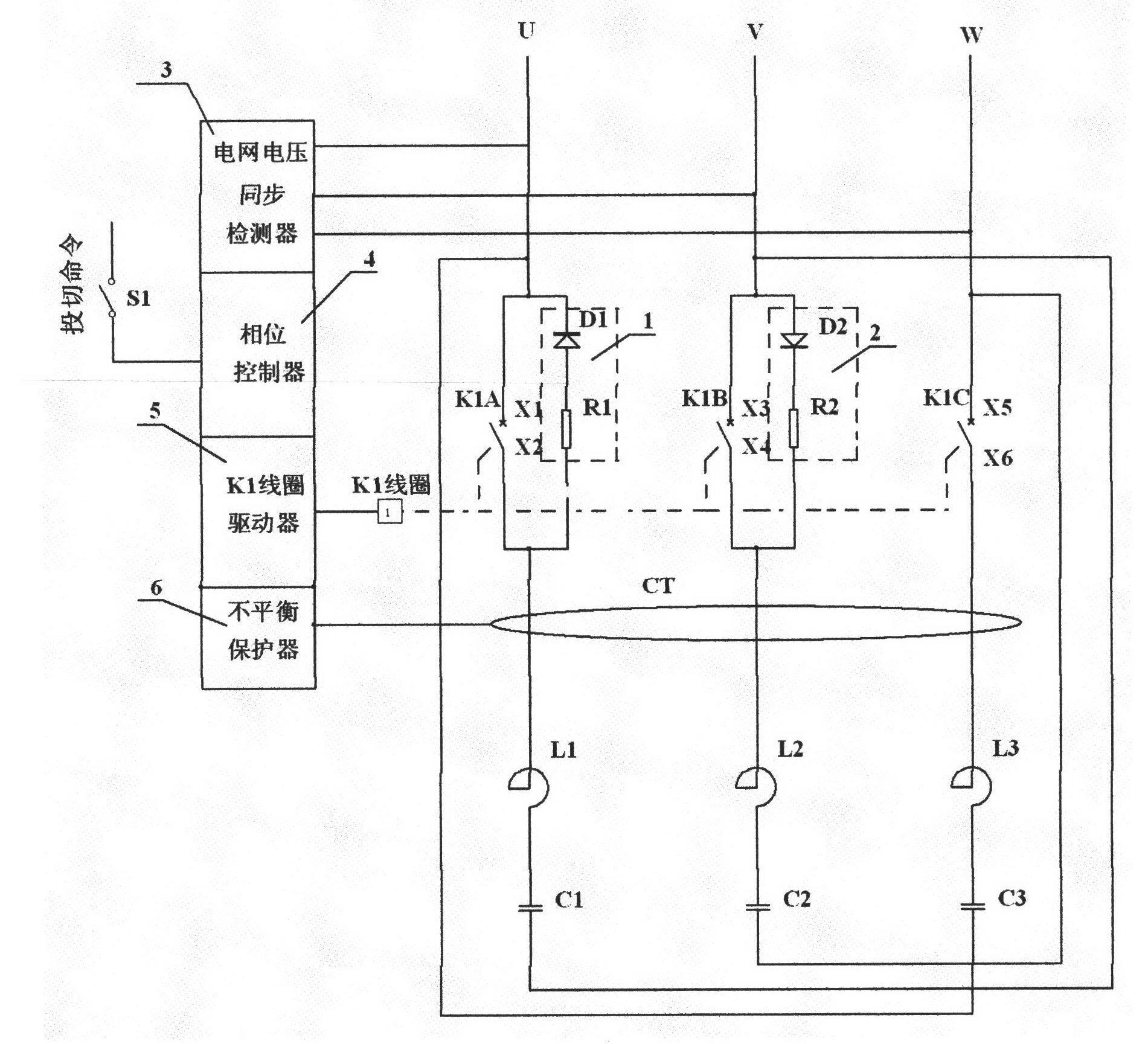
[0028] figure 1 An embodiment of an intelligent reactive power compensation device based on a single three-pole synchronous switch according to the present invention is described, wherein the capacitor bank composed of reactors L1, L2, L3 and capacitors C1, C2, C3 is connected into a delta circuit form. The input terminals X1, X3, and X5 of the three main contacts K1A, K1B, and K1C of the three-pole synchronous switch K1 are connected to the three-phase grid voltage U, V, and W respectively, and the three main contacts K1A of the three-pole synchronous switch K1 The output terminals X2, X4 and X6 of , K1B and K1C are respectively connected in series with the capacitor bank, and the three main contacts K1A, K1B and K1C of the three-pole synchronous switch K1 are installed in the capacitor bank circuit, among which the input terminal of the main contact K1A The pre-charging circuit 1 is connected in parallel between X1 and the output terminal X2, the pre-charging circuit 2 is c...


PUM


Abstract

The invention provides an intelligent reactive compensation device based on a single three-pole synchronous switch. The intelligent reactive compensation device is characterized in that a capacitor bank consists of a reactor and a capacitor connected in a form of a triangular circuit; three main contacts of a three-pole synchronous switch K1 are mounted in the triangular circuit, and are serially connected with the capacitor bank; a pre-charging circuit (1) is connected between the input end and the output end of one main contact in parallel; a pre-charging circuit (2) is connected with the input end and the output end of another main contact in parallel; the capacitor bank is pre-charged by the line voltage of a grid through the pre-charging circuit (1) and the pre-charging circuit (2); a phase control device switches on and off the three main contacts of the three-pole synchronous switch K1 at the same time according to the phase angle of a predetermined grid voltage so as to switch the capacitor bank; and a CT (current transformer) is used for detecting the summation current in the triangular circuit for imbalance protection. The experimental waveform shows that the intelligent reactive compensation device provided by the invention is excellent in electric switching, green, energy-saving, simple in structure, economic and practical, and is good to wide engineering application.

Description

technical field [0001] The invention relates to the fields of reactive power compensation, harmonic filtering and grid power quality control of electric power systems, and in particular to an intelligent reactive power compensation device based on a single three-pole synchronous switch. Background technique [0002] The power grid needs reactive power compensation to achieve the purpose of stabilizing the grid voltage, improving the power factor, and reducing line loss. Switching capacitor bank is the main method to realize reactive power compensation. However, the technical status of switching capacitor bank is not optimistic. [0003] In the field of reactive power compensation, about 80% use mechanical contact switches to switch capacitors. The mechanical contact switches are three-pole switches. The three main contacts of the three-pole switch are closed and opened at the same time. The voltage phase angle switches the capacitor, and the current when it is switched in e...

Claims


Application Information

Patent Timeline
IPC IPC(8): H02J3/18H02H7/06
CPCY02E40/32Y02E40/30
Inventor 杨建宁
Owner 北京馨容纵横科技发展有限公司
Features
  • R&D
  • Intellectual Property
  • Life Sciences
  • Materials
  • Tech Scout
  • Unparalleled Data Quality
  • Higher Quality Content
  • 60% Fewer Hallucinations
Learn More