Buck-Boost voltage-regulating type voltage balance converter

A voltage balancing and voltage regulating technology, applied in the direction of conversion equipment without intermediate conversion to AC, can solve the problems of inability to meet the requirements of input voltage, low voltage, and high input voltage, and improve application flexibility and operational reliability. , DC voltage stability, simple and effective control principle

Inactive Publication Date: 2012-07-25
ZHEJIANG UNIV
View PDF6 Cites 7 Cited by
  • Summary
  • Abstract
  • Description
  • Claims
  • Application Information

AI Technical Summary

Problems solved by technology

In the DC distribution network, the use of two DC lines to transmit electric energy (that is, the unipolar DC distribution network) often cannot meet the input voltage requirements of various power converters and electrical equipment.
For example, for a half-bridge inverter and a full-bridge inverter with the same output voltage, the input voltage of the half-bridge inverter is about twice that of the full-bridge inverter, and it is inconvenient to connect to the unipolar DC distribution network at the same time; The voltage required for lighting circuits is relatively low, while the input voltage required for household appliances such as refrigerators and air conditioners is relatively high, and the unipolar DC distribution network cannot simultaneously meet the input voltage requirements of various electrical equipment

Method used


Image

  • Buck-Boost voltage-regulating type voltage balance converter
  • Buck-Boost voltage-regulating type voltage balance converter
  • Buck-Boost voltage-regulating type voltage balance converter

Examples


Embodiment Construction

[0036] The present invention will be further described below in conjunction with accompanying drawing.

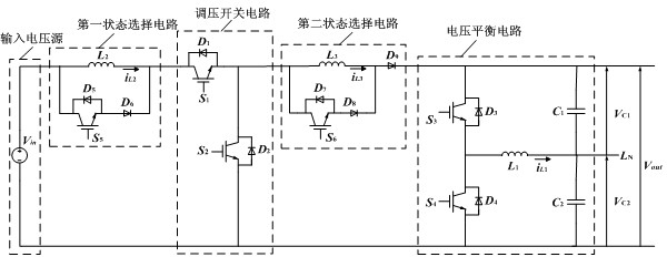
[0037] Such as figure 1 As shown, the present invention includes an input voltage source, a voltage regulating switch circuit, a voltage balance circuit, a first state selection circuit, and a second state selection circuit.

[0038] The voltage regulating switch circuit includes a first power switch tube S 1 , the first power diode D 1 , the second power switch tube S 2 , the second power diode D 2 . first power switch tube S 1 collector with the first power diode D 1 Cathode, the second inductance in the first state selection circuit L 2 Connected at one end, the first power switch tube S 1 emitter and first power diode D 1 Anode, second power switch tube S 2 collector, second power diode D 2 Cathode, the third inductance in the second state selection circuit L 3 Connected at one end, the second power switch tube S 2 emitter and second power diod...


PUM


Abstract

The invention discloses a Buck-Boost voltage-regulating type voltage balance converter. When an input DC voltage of the traditional converter greatly fluctuates, an output DC voltage of the traditional converter is instable. The Buck-Boost voltage-regulating type voltage balance converter comprises an input voltage source, a voltage-regulating switch circuit, a voltage balance circuit, a first state selection circuit and a second state selection circuit, wherein a first power switch tube S1 is connected in parallel with a diode D1; a second power switch tube S2 is connected in parallel with a diode D2; a third power switch tube S3 is connected in parallel with a diode D3; a fourth power switch tube S4 is connected in parallel with a diode D4; a fifth power switch tube S5 is connected in parallel with a diode D5, a sixth diode D6 and a second inductance L2; and a sixth power switch tube S6 is connected in parallel with a diode D7, an eighth diode D8, a ninth diode D9 and a third inductance L3. The Buck-Boost voltage-regulating type voltage balance converter can maintain that voltages at two ends of a DC voltage-dividing capacitor when loads at two poles of a DC power distribution network are not balanced; and when the input DC voltage greatly fluctuates, the output DC voltage is maintained to be stable.

Description

technical field [0001] The invention belongs to the application field of power electronics, in particular to a Buck-Boost voltage regulation type voltage balance converter. Background technique [0002] With the rapid development and wide application of new energy, new materials, information technology and power electronics technology, as well as the continuous improvement of users' requirements for power consumption, power quality and power supply reliability, the distribution network based on DC will definitely be more and more popular. more and more attention. In the DC distribution network, the use of two DC lines to transmit electric energy (that is, the unipolar DC distribution network) often cannot meet the input voltage requirements of various power converters and electrical equipment. For example, for a half-bridge inverter and a full-bridge inverter with the same output voltage, the input voltage of the half-bridge inverter is about twice that of the full-bridge i...

Claims


Application Information

Patent Timeline
Patent Type & Authority Applications(China)
IPC IPC(8): H02M3/10
Inventor 郑欢江道灼
Owner ZHEJIANG UNIV
Why Eureka
Try Eureka