
Internal screw thread processing method

An internal thread processing and internal thread technology, applied in thread cutting tools, metal processing equipment, manufacturing tools, etc., can solve the problems of letting the knife and the knife not be too deep, and the product quality cannot be guaranteed, and achieve the effect of increasing the support

Inactive Publication Date: 2012-08-01
德阳宝特机械设备有限责任公司
View PDF7 Cites 14 Cited by
  • Summary
  • Abstract
  • Description
  • Claims
  • Application Information

AI Technical Summary

Problems solved by technology

[0007] In order to overcome the existing internal thread processing method when processing slender workpieces or workpieces with an aspect ratio greater than 10, the deflection generated at the blade is too large, which is easy to cause the knife to give way, and the knife should not be too deep, and the Reduce production efficiency and can not guarantee the quality of the product, now a special internal thread processing method is proposed

Method used


Image

  • Internal screw thread processing method
  • Internal screw thread processing method
  • Internal screw thread processing method

Examples


Embodiment 1

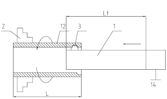
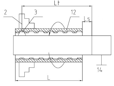
[0066] Below in conjunction with accompanying drawing this patent is described, in figure 1 and figure 2 Among them, f1= , where f1 is the deflection, also known as the amount of deformation, P is the cutting force, L is the length of the workpiece, E is the modulus of elasticity, and I is the moment of inertia. At this time, if the gap length Ls of the tool bar is ignored, the cantilever length Lt of the tool bar Approximately equal to the length L of the workpiece, the deflection of the tool holder at the blade is f1. However, when processing slender internal threads (for example, the diameter of the thread is less than 20mm, or the ratio of the length to the diameter of the thread is greater than 10 at the same time), because the tool shaft is thin and only the force is applied to the front end blade, it becomes a cantilever beam. The resulting deflection is too large, it is easy to produce a knife, and the knife cannot be too deep, which not only reduces the production...

Embodiment 2

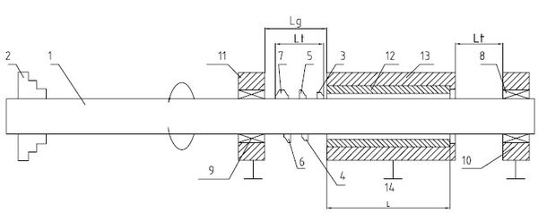
[0072] If the length-to-diameter ratio of the internal thread is not too large, the openable bearing on the left ( Figure 8 ), at this time, the length Lw between the two supports of the tool bar is approximately equal to twice the length L of the workpiece, and the deflection of the tool bar at the blade is f3, f3= = = , f3 / f1=1 / 2, that is to say, the deflection of the tool holder is only 1 / 2 of the traditional processing method.

Embodiment 3

[0074] There are two methods of thread tooth shape.

[0075] The first type: several pieces of cutting section can be used to be the same or similar to the profile of the thread to be processed but the height ( Figure 9 Middle Ht) Different blades f, blade g and blade h are cut in sequence, and finally the entire tooth profile is processed. This method is generally applicable to threads with small tooth profiles such as triangular threads and rectangular threads.

[0076] The second type: use several blades that are different in shape from the tooth shape but can cover the entire tooth shape after being superimposed ( Figure 10 Middle blade a, blade b, blade c, blade d) are cut in sequence, and finally the entire tooth shape is processed. This method is generally suitable for trapezoidal threads or other threads with complex tooth shapes and large tooth profile sections.

[0077] Regardless of the first or second division method, if in order to improve the accuracy of the p...


PUM


Abstract

The invention relates to the technical field of mechanical processing, in particular to an internal screw thread processing method. The method is concretely characterized in that a cutter rod is arranged on a lathe, the two ends of the cutter rod are fixed, one end of the cutter rod is arranged on a chuck of a main shaft of the lathe, the other end of the cutter rod is arranged on a bearing, the chuck is arranged on the main shaft of the lathe, a cutter blade is arranged on the cutter rod, a workpiece requiring the internal screw thread processing is arranged on a cutter frame, the cutter frame is arranged on a slide plate box of the lathe, when the cutter rod and the cutter blade arranged above the cutter rod are driven to rotate by the main shaft, the workpiece is driven to do linear movement in the bus direction on the cutter rod by the slide plate box, and in the moving process, the cutter blade positioned in the hollow part of the workpiece carries out screw thread processing on the inner wall of the workpeice in the rotating process. The internal screw thread processing method has the advantages that the support is added to the cutter rod, in order to add the support to the cutter rod, the moving mode of the cutter and the workpiece firstly needs to be changed, through the method, the cutter only does rotating movement, and meanwhile, the workpiece and the cutter only do relative linear movement.

Description

technical field [0001] The invention relates to the technical field of mechanical processing, in particular to an internal thread processing method. Background technique [0002] There are two main methods of thread processing: turning and milling. Turning is used to process rotary parts. The parts are clamped on the spindle of the machine tool through a three-jaw chuck and rotated. Then, the turning tool is used to move along the generatrix of the rotary body to cut out the shape of the product. The lathe can also process inner holes, threads, bites, etc., and the latter two are low-speed processing. And milling is to fix the blank, and use a high-speed rotating milling cutter to move on the blank to cut out the required shape and features. Traditional milling is mostly used for simple shapes / features such as milling contours and slots. CNC milling machines can process complex shapes and features as well as internal threads. [0003] The method of machining the internal...

Claims


Application Information

Patent Timeline
Patent Type & Authority Applications(China)
IPC IPC(8): B23G1/04B23G1/46B23G1/44B23G5/00
Inventor 孙珏汪瑜
Owner 德阳宝特机械设备有限责任公司
Learn More