Servo mechanical press

A technology for servo machinery and presses, applied in the field of six-link servo mechanical presses, can solve the problems of inability to adapt to the servo stamping process, and the slider can only change speed, and achieves simple structure, large force increase stroke, and reduced manufacturing costs. Effect

Inactive Publication Date: 2012-08-01
SHUNDE POLYTECHNIC
View PDF16 Cites 23 Cited by
  • Summary
  • Abstract
  • Description
  • Claims
  • Application Information

AI Technical Summary

Problems solved by technology

In this scheme, the power of the servo motor is small, but there are problems that the output power of different types of motors cancel each other ou

Method used


Image

  • Servo mechanical press
  • Servo mechanical press
  • Servo mechanical press

Examples


Embodiment 1

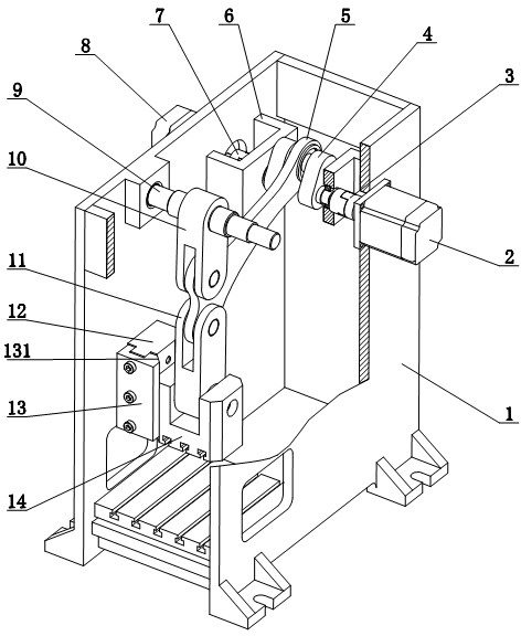
[0021] Such as figure 1 As shown, a servo mechanical press includes a frame 1, and the frame 1 is in a frame shape; the present invention is characterized in that it also includes a synchronous first servo motor 2, a second servo motor 8, a first reduction mechanism, a second Two deceleration mechanisms, a six-link working mechanism and a guide structure; wherein the first servo motor 2 and the second servo motor 8 are symmetrically installed on both sides of the frame 1, and the first deceleration mechanism and the second The reduction mechanism is symmetrically installed on both sides of the frame 1; the six-link working mechanism is installed in the frame of the frame 1; the input end of the first reduction mechanism is coaxial with the output shaft of the first servo motor 2, The output end of the first reduction mechanism is fixedly connected with the crankshaft right input end of the six-link working mechanism, the input end of the second reduction mechanism is coaxial w...

Embodiment 2

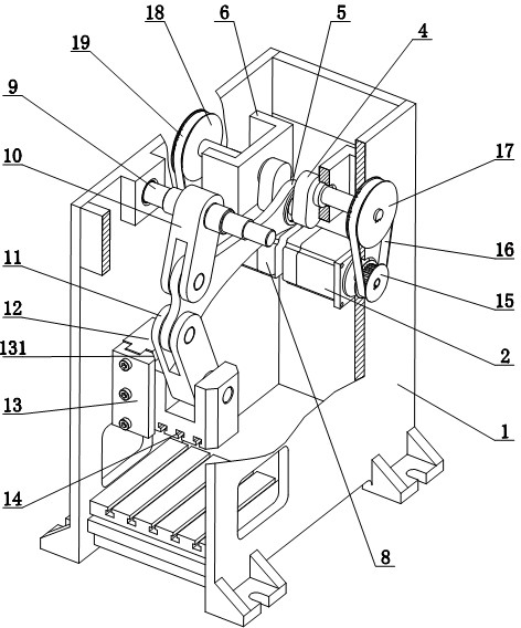
[0027] Such as figure 2 As shown, this embodiment is basically the same as Embodiment 1, and the difference is that: the structure of the first deceleration mechanism is the same as that of the second deceleration mechanism, and the first deceleration mechanism includes a first small synchronous pulley 15, a first synchronous belt 16 And the first large synchronous pulley 17, the first small synchronous pulley 15 is installed on the output shaft of the first servo motor 2, the first large synchronous pulley 17 is coaxial with crankshaft 4, the first synchronous belt 16 Set on the first small synchronous pulley 15 and the first large synchronous pulley 17, the first small synchronous pulley 15 drives the first large synchronous pulley 17 through the first synchronous belt 16; the second reduction mechanism includes the second small synchronous pulley (not shown), the second synchronous belt 19 and the second large synchronous pulley 18, the second small synchronous pulley is i...

Embodiment 3

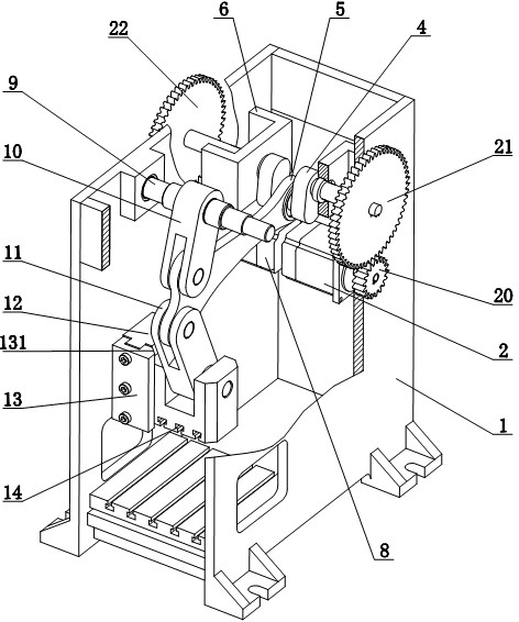
[0029] Such as image 3 As shown, this embodiment is basically the same as Embodiment 1, and the difference is that: the structure of the first reduction mechanism and the second reduction mechanism are the same, and the first reduction mechanism includes a first small gear 20 and a first large gear 21, so The first small gear 20 is installed on the output shaft of the first servo motor 2, the first large gear 21 is coaxial with the crankshaft 4, and the first small gear 20 meshes with the first large gear 21; the second reduction mechanism includes the first Two small gears (not shown in the figure) and the second large gear 22, the second small gear is installed on the output shaft of the second servo motor 8, the second large gear 22 is coaxial with the crankshaft 4, the second The pinion meshes with the second large gear 22 . In addition, the first servo motor 2 and the second servo motor 8 are symmetrically arranged and installed on two inner sides of the frame 1 .


PUM


Abstract

The invention relates to a servo mechanical press which comprises a stand shaped like a frame, and is characterized by further comprising a first synchronous servomotor, a second synchronous servomotor, a first retarding mechanism, a second retarding mechanism, a six-link type working mechanism and a guiding mechanism, wherein the first synchronous servomotor and the second synchronous servomotor are mounted on two sides of the stand in an eudipleural manner; the first retarding mechanism and the second retarding mechanism are mounted on two sides of the stand in an eudipleural manner; the six-link type working mechanism is mounted in the frame of the stand; an input end of the first retarding mechanism is coaxially arranged with an output shaft of the first servomotor; an output shaft of the first retarding mechanism is fixedly connected with an input end on the right side of a crankshaft of the six-link type working mechanism; an input end of the second retarding mechanism is coaxially arranged with an output end of the second servomotor; an output end of the second retarding mechanism is fixedly connected with an input end on the left side of the crankshaft of the six-link type working mechanism; the guiding mechanism is mounted in the frame of the stand; and a slide block at the output end of the six-link type working mechanism is positioned in the guiding mechanism and can move up and down. The invention provides the servo mechanical press, which has a simple structure, is convenient to control, can reduce the output torque and the required capacity of the servomotors, and can be built with large tonnage and low cost.

Description

technical field [0001] The invention relates to a device in the technical field of forging machinery, in particular to a six-link servo mechanical press driven in parallel by double servo motors. Background technique [0002] The servo mechanical press is a new type of metal forming equipment using servo drive technology. Due to relying on the controllable drive element—servo motor—to provide power, the servo mechanical press not only has the high motion flexibility of the hydraulic press, but also has the high production efficiency of the mechanical press, and also has the advantages of improving product quality, saving energy consumption and reducing working noise. Advantages are an important development direction of forging equipment in the future. [0003] Most of the ordinary mechanical presses are crank presses driven by asynchronous motors. Generally, a large flywheel that stores and releases energy is designed and installed on the high-speed shaft of its transmissi...

Claims


Application Information

Patent Timeline
IPC IPC(8): B30B1/02B30B15/14
Inventor 胡建国雷德沛
Owner SHUNDE POLYTECHNIC
Why Eureka
Try Eureka