
Carbon fiber tent rack

A carbon fiber tube and tent technology, applied in the field of carbon fiber tent brackets, can solve the problems of long production cycle, impact on structural strength, and heavy metal tube materials, and achieve the effects of reducing erection and dismantling time, improving structural strength, and reducing volume

Inactive Publication Date: 2012-08-01
THE QUARTERMASTER EQUIPMENT RESEARCH INSTITUTE OF THE GENERAL LOGISITIC DEPARTME +1
View PDF9 Cites 1 Cited by
  • Summary
  • Abstract
  • Description
  • Claims
  • Application Information

AI Technical Summary

Problems solved by technology

Inflatable tents are made of air-tight materials to form air columns, which are bonded to form structural parts. The problem is that additional inflatable equipment is required. If the temperature difference between day and night is too large, air needs to be replenished, and the structural strength will be greatly affected after air leakage; In addition, inflatable tents are mostly made of polymer materials such as rubber and PVC, which have a strong smell; moreover, the production cycle is long and the process is relatively complicated.
Most of the scaffolding tents use metal pipes to form structural parts. The problem is that the metal material has a large specificity, low modulus, and the structural strength is affected.
The common defect of the above two kinds of tents is that the support materials of the tents are either composed of inflatable air columns that need to be equipped with additional inflatable equipment, or are composed of bulky metal tubular materials. This type of tent seriously limits the mobility of troops during marching operations. flexibility

Method used


Image

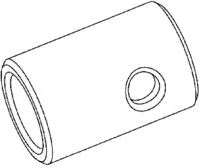
  • Carbon fiber tent rack
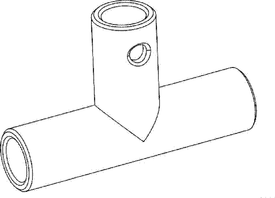
  • Carbon fiber tent rack
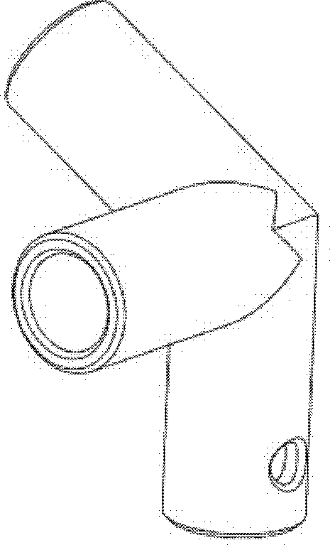
  • Carbon fiber tent rack

Examples


Embodiment 1

[0037] Embodiment 1, carbon fiber tent support

[0038] The tent frame consists of some carbon fiber tubes, some plastic (polyamide) connectors 1-6 and some screws. The tube walls at both ends of the carbon fiber tube are provided with through holes for passing through the screws, and the tube walls of at least one port edge of the connector are provided with through holes for passing through the screws, The carbon fiber tube and the connector adopt a direct plug-in connection structure and are fastened with screws;

[0039] Wherein, the outer diameter of the carbon fiber tube is 32mm, the thickness of the tube wall is 3.2mm, and the length is 1880mm; the aperture of the hole set on the tube wall at both ends of the carbon fiber tube is 3mm, and the chamfer of the hole is 45 degrees. The distance between the center of the hole and the end surface of the carbon fiber tube close to it is 30 mm.

[0040] The pipe diameter specifications of the carbon fiber pipes constituting th...


PUM

PropertyMeasurementUnit
Outer diameteraaaaaaaaaa
Tube wall thicknessaaaaaaaaaa
Lengthaaaaaaaaaa

Abstract

The invention discloses a tent rack. The tent rack comprises a plurality of carbon fiber pipes, a plurality of plastic fittings and a plurality of screws, wherein through holes where screws pass are arranged on the pipe walls of edges of two ends of the carbon fiber pipes and on the pipe walls of edges of at least one ends of the plastic fittings, and the carbon fiber pipes and the plastic fittings are connected through a direct plugging structure and are fastened through screws; the tent rack comprises a square base and at least one support unit; the square base is formed by a front bottom beam, a left bottom beam, a back bottom beam and a right bottom beam which are sequentially connected through the fitting 6; the front bottom beam and the back bottom beam are formed through the connection of two carbon fiber pipes through the fitting 1, and the left bottom beam and the right bottom beam are formed by one carbon fiber pipe or through the connection of two carbon fiber pipes through the fitting 2; and the support unit is a V-shaped ceiling rack formed by three purlines, four cant beams and four upright columns. The carbon fiber tent rack has the capabilities of improving the structural strength of a tent, reducing the weight and the volume of the tent, and shortening time for assembling and disassembling.

Description

technical field [0001] The invention relates to a carbon fiber tent frame. Background technique [0002] Generally, tents include two categories: inflatable tents and bracket tents. Inflatable tents are made of air-tight materials to form air columns, which are bonded to form structural parts. The problem is that additional inflatable equipment is required. If the temperature difference between day and night is too large, air needs to be replenished, and the structural strength will be greatly affected after air leakage; In addition, inflatable tents are mostly made of polymer materials such as rubber and PVC, which have a strong smell; moreover, the production cycle is long and the process is relatively complicated. Most scaffolding tents use metal pipes to form structural parts. The problem is that the metal material has a large specificity, low modulus, and the structural strength is affected. The common defect of the above two kinds of tents is that the support materia...

Claims


Application Information

Patent Timeline
IPC IPC(8): E04H15/44
Inventor 马天张建春张相洪杨涵李燕军沈凤川严自力张华陆国军马永明黄忆婷
Owner THE QUARTERMASTER EQUIPMENT RESEARCH INSTITUTE OF THE GENERAL LOGISITIC DEPARTME
Learn More