Instrument for monitoring gas emission quantity in roadway

A technology of gas emission and monitoring instrument, which is applied in the direction of mining equipment, mining equipment, earth square drilling and mining, etc., to achieve the effect of convenient query and convenient query

Active Publication Date: 2012-08-01
SHANDONG UNIV OF SCI & TECH
5 Cites 20 Cited by

AI-Extracted Technical Summary

Problems solved by technology

In short, there is no effective method for monitoring the gas influx in the roadway, and the...

Method used

[0030] Referring to Fig. 2, the gas emission monitor of embodiment 1 includes a monitor main body 9 and a keyboard input and a liquid crystal display part 10. The gas concentration sensor 2 and the wind speed sensor 4 are arranged in the main body of the monitor. The gas concentration sensor probe 11 and the wind speed sensor probe 12 are connected to the sensor main body through signal lines. The two probes can be extended or retracted from the monitor main body, which is convenient The sensor probes are in different locations. The gas concentration sensor probe and wind speed sensor probe are used to detect gas concentration and wind speed information respectively. Two buttons 13 are designed on the main body 9 of the gas monitor, and the gas concentration sensor probe 11 and the wind speed sensor probe 12 can be conveniently extended and retracted, so as to facilitate the placement and detection of the probes and prevent damage to the probes when moving. The keyboard input and display part 10 includes: a liquid crystal display 8 and a numeric keypad 6 . The liquid ...

Abstract

The invention discloses an instrument for monitoring gas emission quantity in a roadway. The instrument mainly comprises a data processing module, a gas concentration sensor, a wind speed sensor, a signal conditioning circuit, an A/D (Analog/Digital) converter, a digital keyboard, a liquid crystal display and an upper computer, wherein the data processing module is used for receiving and storing a gas concentration signal and a wind speed signal after conversion, calculating to obtain the gas emission quantity, and outputting the gas emission quantity, the gas concentration and the wind speed at the same time; the digital keyboard is used for inputting the cross section information of the roadway; the signal conditioning circuit is used for amplifying and filtering an analogue signal; the A/D converter is used for converting the analogue signal into a corresponding digital signal; and the upper computer is used for acquiring the wind speed, the gas concentration and the gas emission quantity output after the analysis of the data processing module, calculating, processing and displaying a time-varying curved line of the wind speed, the gas concentration and the gas emission quantity of the measured point. The instrument is real-time, quick and accurate, and is particularly suitable for real-time monitoring and warning of burst or emission of a large amount of gases.

Application Domain

Technology Topic

Image

  • Instrument for monitoring gas emission quantity in roadway
  • Instrument for monitoring gas emission quantity in roadway
  • Instrument for monitoring gas emission quantity in roadway

Examples

  • Experimental program(1)

Example Embodiment

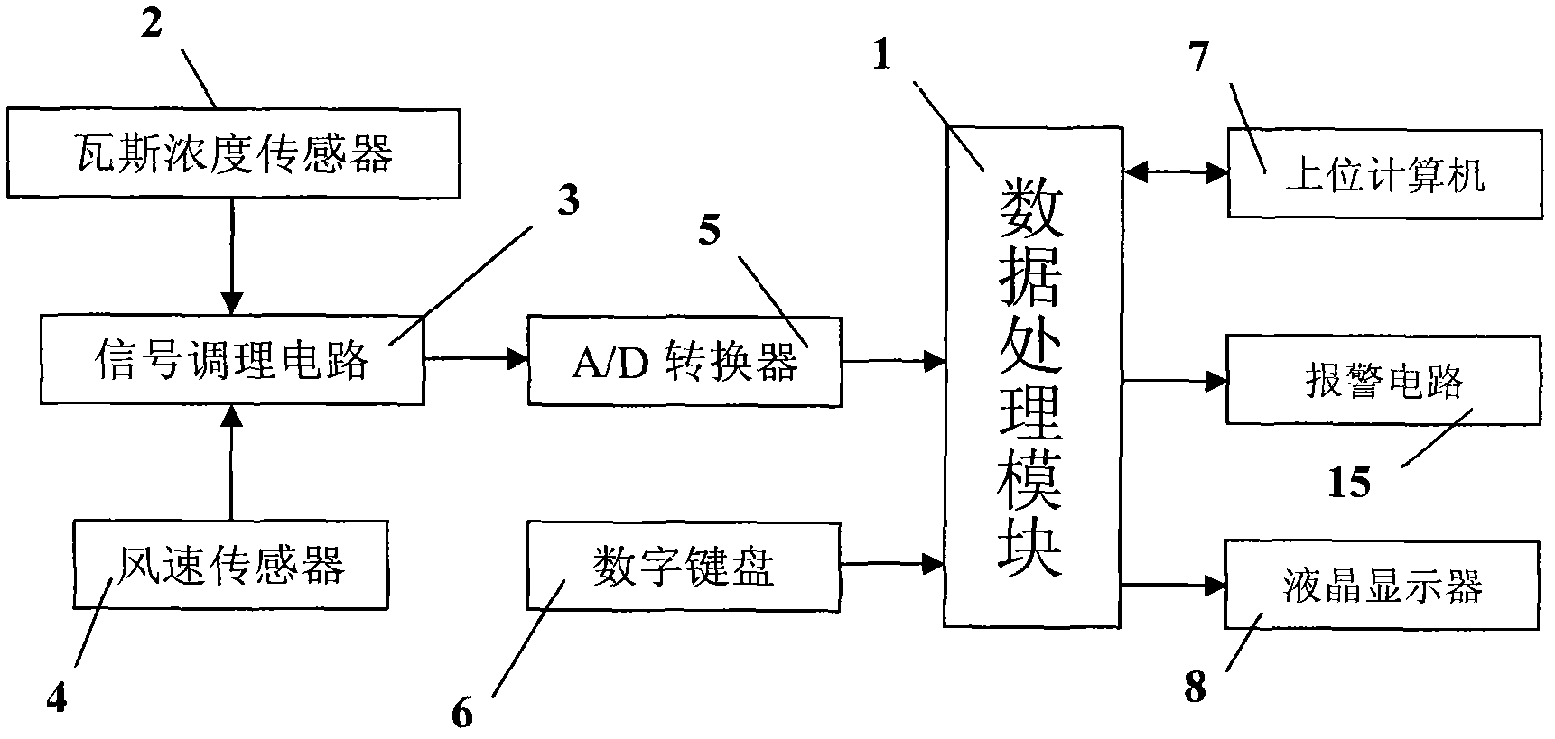
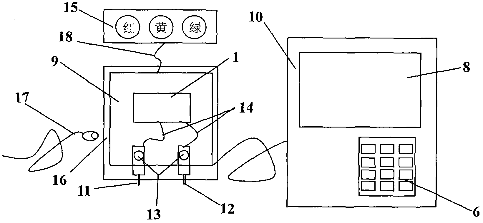
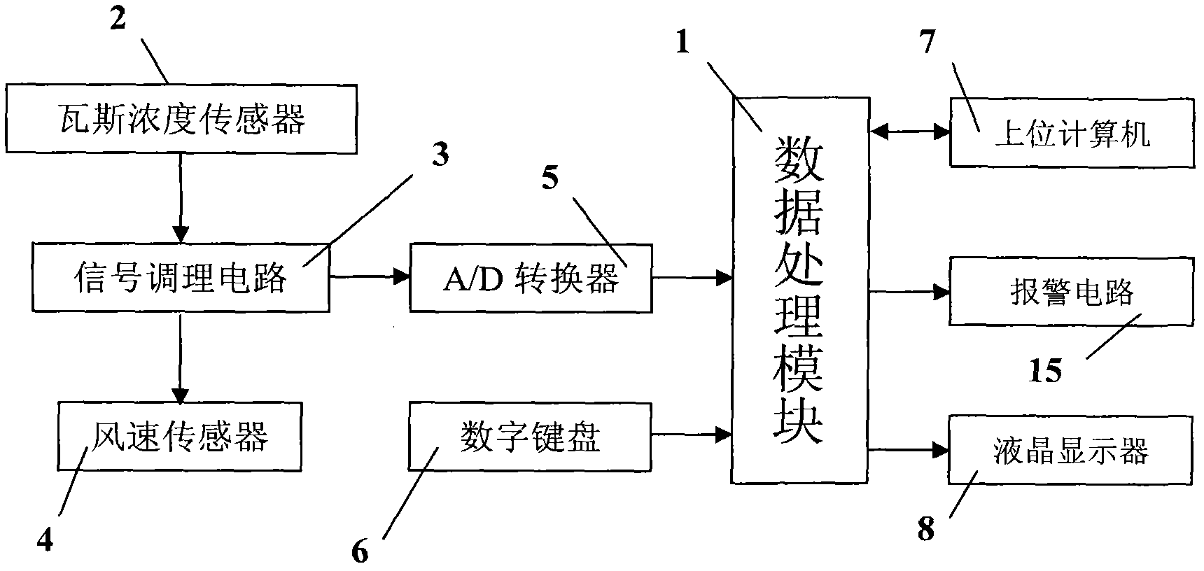
[0028] The present invention will be further described in detail below with reference to the drawings and embodiments.
[0029] See figure 1 , Example 1 A gas emission monitoring instrument in a tunnel, including a data processing module 1, containing MSP430 series single-chip microcomputer, memory and peripheral circuits, used to store and analyze and process data, according to the formula Q=GVS and numeric keyboard 6 input Calculate the gas emission from the tunnel section information, and output the gas emission together with the gas concentration and wind speed at the same time, where Q is the gas emission, G is the gas concentration, V is the wind speed, and S is the tunnel cross-sectional area. Gas concentration sensor 2, used to detect gas concentration information. The signal conditioning circuit 3 composed of an amplifier circuit and a filter circuit is used to amplify and filter the gas concentration signal and the wind speed signal detected by the gas concentration sensor 2 and the wind speed sensor 4. The wind speed sensor 4 is used to detect wind speed information. The A/D converter 5 is used to convert the amplified and filtered analog signal into a digital signal and input it to the data processing module 1. The numeric keyboard 6 is used to input the information of the tunnel section into the data processing module 1. The upper computer 7 is used to collect the wind speed, gas concentration and gas emission data output after analysis and processing by the data processing module 1, and to calculate and display the wind speed, gas concentration and gas emission volume curve of the measured point with time. The liquid crystal display 8 is used to display the wind speed, gas concentration and gas emission information output by the data processing module 1.
[0030] See figure 2 , Example 1 The gas emission monitor includes the monitor main body 9 and the keyboard input and liquid crystal display part 10. The gas concentration sensor 2 and the wind speed sensor 4 are arranged in the main body of the monitor. The gas concentration sensor probe 11 and the wind speed sensor probe 12 are connected with the sensor body through signal lines. The two probes can be extended or retracted from the main body of the monitor for convenience The sensor probes are in different positions. Gas concentration sensor probe and wind speed sensor probe are used to detect gas concentration and wind speed information respectively. There are two buttons 13 on the main body 9 of the gas monitor, which can easily extend and retract the gas concentration sensor probe 11 and the wind speed sensor probe 12 to facilitate the placement and detection of the probe and prevent the probe from being damaged when moving. The keyboard input and display part 10 includes: a liquid crystal display 8 and a numeric keyboard 6. The liquid crystal display 8 is used to display gas concentration, wind speed and gas emission, and the numeric keyboard 6 is used to input information of the roadway section. The data processing module 1 is arranged in the main body 9 of the monitor, and is connected to the sensor through a data line 14, connected to the alarm circuit 15 through the data line 18, and connected to the upper computer through the data line 17. 16 is an explosion-proof device, which protects the probe but does not affect the measurement.
[0031] Install the instrument at a suitable location in the roadway. When there is gas gushing or gas outburst in the roadway, the gas concentration sensor probe 11 and the wind speed sensor probe 12 measure the relevant data, and then calculate the gas emission value. Compare with the upper and lower limits of the safety value of gas emission stored in the data processing module 1. The upper and lower limits of the safety value of gas emission need to be stored in advance. Considering that the wind speed range in the roadway is 4m/s-8m/s, the gas concentration range is 0.8%-5%. Comprehensive various factors, set the gas emission when the yellow light is on The range is 6% S-20% S, where S is the cross-sectional area of ​​the roadway. When the measured gas emission exceeds the upper limit of the safe value by 20%S, the alarm circuit 15 will display a red light and alarm; when the measured gas emission is lower than the lower limit of the safe value by 6%S, the alarm circuit 15 will display a green light; If the gas emission amount is between the upper and lower limits of the safety value, the alarm circuit 15 displays a yellow light. After the alarm is generated, the real-time monitoring results can be viewed through the upper computer immediately, so that relevant measures can be taken in time. When there is no large amount of gas in the tunnel, you can also use the curve obtained by the upper computer to study the change law of the gas emission.
[0032] The gas emission monitoring instrument in the roadway of the present invention solves the problem of the untimely and inaccurate measurement of the gas emission under the gas outburst environment in the roadway, and the monitoring result is faster and more accurate. It can output gas concentration, wind speed and gas emission information at the same time, and it is convenient to query various data of each measurement point in the roadway after gas outburst. It can display the change curve of gas emission in real time, which is beneficial to accurately analyze the change law of gas emission in the tunnel.

PUM

no PUM

Description & Claims & Application Information

We can also present the details of the Description, Claims and Application information to help users get a comprehensive understanding of the technical details of the patent, such as background art, summary of invention, brief description of drawings, description of embodiments, and other original content. On the other hand, users can also determine the specific scope of protection of the technology through the list of claims; as well as understand the changes in the life cycle of the technology with the presentation of the patent timeline. Login to view more.

Similar technology patents

Mobile information intelligent nursing station

InactiveCN103110461AConvenient queryReduce doctor-patient disputesEnergy efficient ICTSurgeryFingerprintLocal area network
Owner:SUZHOU DERPIN MEDICAL SCI & TECH CO LTD

Classification and recommendation of technical efficacy words

Why Eureka
Try Eureka