Gear interlocking device for automotive transmission

A technology of automobile transmission and interlocking device, which is applied in transmission control, components with teeth, belts/chains/gears, etc. It can solve problems such as inability to interlock, large relative distance between shift fork shafts, etc., and achieve processing and precision Low requirements, flexible layout, and simple overall structure

Inactive Publication Date: 2012-08-01
GREAT WALL MOTOR CO LTD
View PDF6 Cites 9 Cited by
  • Summary
  • Abstract
  • Description
  • Claims
  • Application Information

AI Technical Summary

Problems solved by technology

[0004] In order to solve the deficiencies in the prior art, the present invention provides an automobile transmission gear interlock device which makes the layout of the shift fork shafts more flexible, and avoids the phenomenon that the relative distance between the shift fork shafts is relatively large and cannot be interlocked. occurs, its structure is simple

Method used


Image

  • Gear interlocking device for automotive transmission
  • Gear interlocking device for automotive transmission
  • Gear interlocking device for automotive transmission

Examples


Embodiment 1

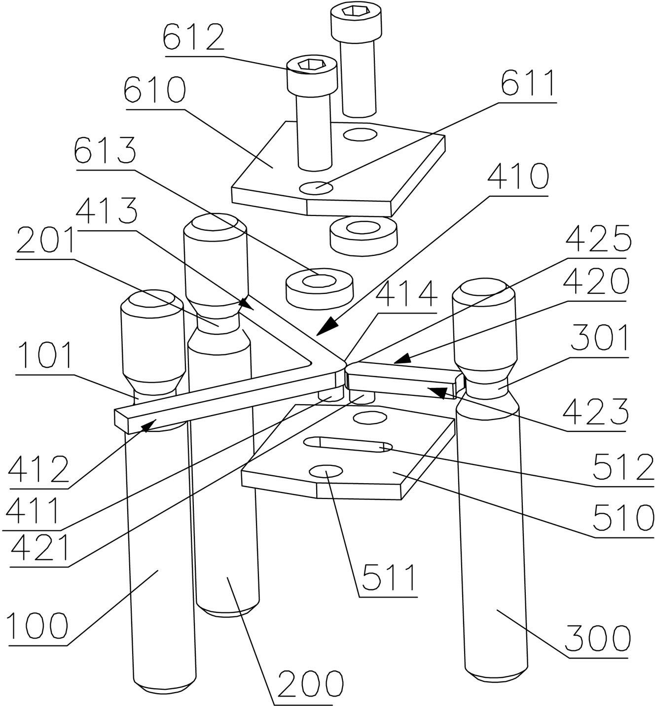
[0024] Such as figure 1 In the gear interlocking device of the automobile transmission in the embodiment shown, there are three shift fork shafts, which are arranged in parallel. Through the axial movement of the shift fork shaft, the gears on the corresponding shafts can be combined or disengaged. Recesses are respectively provided at the same position on the shaft, wherein the first shift fork shaft group includes two shift fork shafts, namely the first shift fork shaft 100 and the second shift fork shaft 200, and the second shift fork shaft group has a The first shift fork shaft, that is, the third shift fork shaft 300, the recessed part provided on each shift fork shaft is used to combine with the locking arm, thereby locking the shift fork shaft, the recessed part in this embodiment is the dial The annular slots provided on the outer wall of the fork shaft are respectively the first slot 101 provided on the first fork shaft 100, the second slot 201 provided on the second ...

Embodiment 2

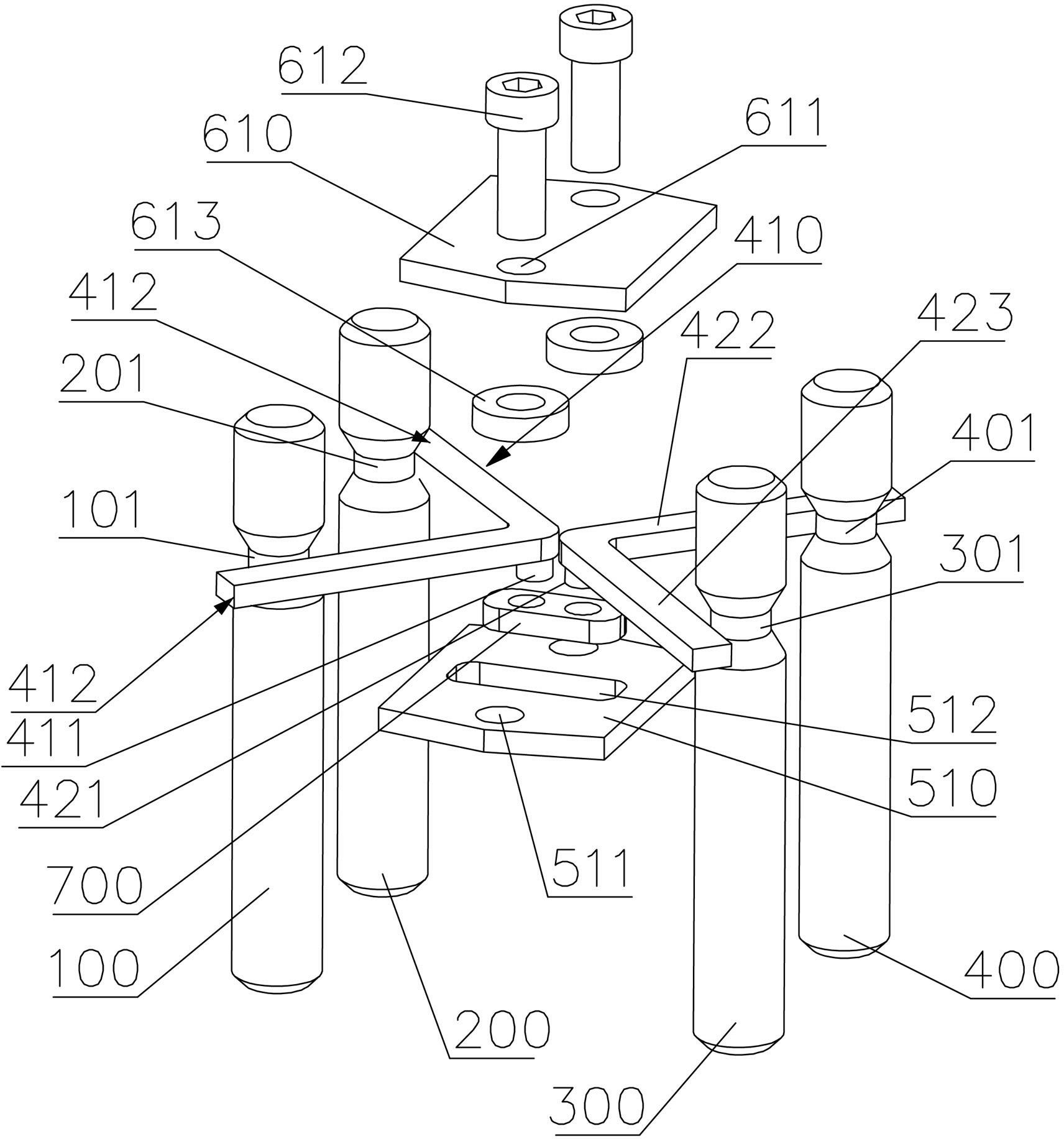
[0032] Such as figure 2 The automobile transmission gear interlocking device of this embodiment shown is different from Embodiment 1 in that this embodiment is applied to the structure of four shift fork shafts, that is, a second shift fork shaft group is also provided with a second shift fork shaft. Four shift fork shafts 400, the fourth shift fork shaft 400 is provided with a corresponding fourth slot 401, correspondingly, the second locking arm group 420 is added with a fourth locking arm 422, and the third locking arm 423 and The fourth locking arm 422 is rigidly connected and has a V shape as a whole. The fourth locking arm 422 can be embedded in the fourth slot 401 to lock the axial movement of the fourth fork shaft 400 . The third locking arm 423 and the fourth locking arm 422 are also combined on the outer side of the second shift fork shaft group.

[0033] In addition, in order to reflect the improvement of the present invention, in this embodiment, a sliding block ...

Embodiment 3

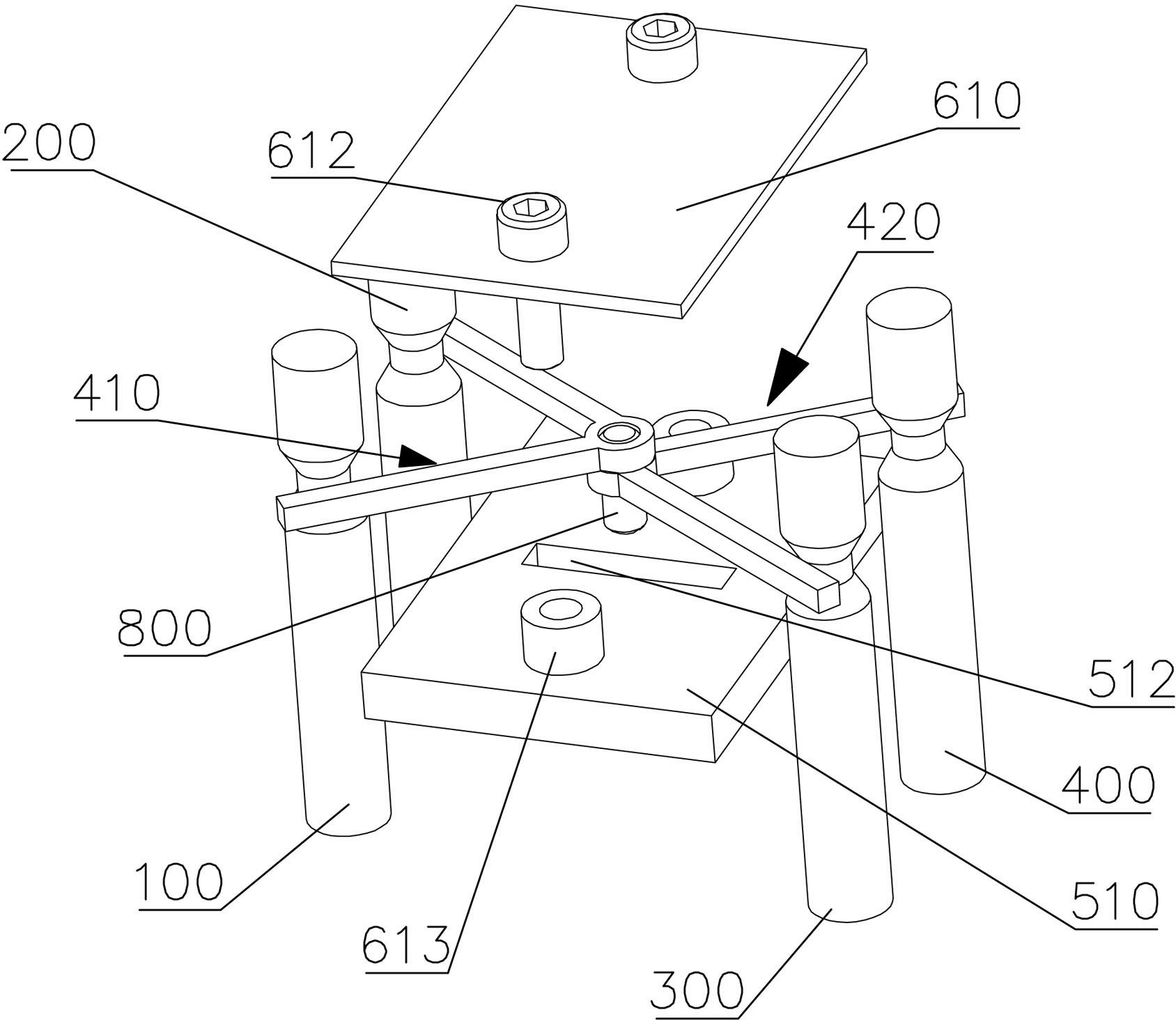
[0037] Such as image 3 The gear interlocking device of the automobile transmission shown in this embodiment is different from the second embodiment in that no slider is added, and the first locking arm group 410 and the second locking arm group 420 are equipped with A through hole, the pin shaft 800 passes through the through hole to form a mutual rotatable connection between the two, and the boss at the front end of the pin shaft enters into the slide groove 512 to form a sliding fit.


PUM


Abstract

The invention relates to a gear interlocking device for an automotive transmission in automobile control structure. The gear interlocking device comprises a first stirring fork shaft group with two stirring fork shafts and a second stirring fork shaft group with a stirring fork shaft. The stirring fork shafts are arranged in parallel. A sunken part is arranged on each stirring fork shaft. A first locking arm group (410) with two rigidly-connected locking arms and a second locking arm group (420) with a locking arm are arranged between the first and second stirring fork shaft groups, are connected to a positioning block which is fixedly connected with an automobile body in a rotating way, and can synchronously and linearly slide relative to the positioning block between the first and second stirring fork shaft groups. By the technical scheme, the stirring fork shafts can be interlocked when distances between every two stirring fork shafts are long, and can be flexibly arranged; and moreover, the overall structure is simple, and machining and accuracy requirements are low.

Description

technical field [0001] The invention relates to a gear interlocking device in an automobile control structure, in particular to an automobile transmission gear interlocking device for interlocking gears of a transmission. Background technique [0002] In the transmission of the power mechanism of automobiles, in order to avoid accidents caused by gears of different gears meshing with the power shaft gear at the same time, it is necessary to realize interlocking between the gears. When the transmission is in a certain gear, drive The shift fork shaft engaged with the shifting gears of the remaining gears can be fixed and locked automatically so that it cannot move. [0003] A commonly used method is to set a slidable slider or steel ball between two shift fork shafts, and a slot for accommodating the slider or steel ball is correspondingly provided on the shift fork shaft. When in the neutral position, the slider or steel ball can move freely. When in gear, a certain shift f...

Claims


Application Information

Patent Timeline
Patent Type & Authority Applications(China)
IPC IPC(8): F16H63/34
Inventor 龚正伟贾玉灵
Owner GREAT WALL MOTOR CO LTD
Why Eureka
Try Eureka