
Automatic scanning device for monitoring coal yard

A technology of automatic scanning and scanning devices, which is applied in the direction of measuring devices, instruments, thermometers, etc., can solve the problems of high construction safety level, low work efficiency, hot-fire welding, etc., and achieve convenient later maintenance, simple construction and debugging, and energy saving Effect

Inactive Publication Date: 2014-02-19
南京卓越能源技术有限公司
View PDF4 Cites 0 Cited by
  • Summary
  • Abstract
  • Description
  • Claims
  • Application Information

AI Technical Summary

Problems solved by technology

[0004] 1. The construction safety level is high and hot welding is required;
[0005] 2. The installation and debugging process of the position sensor is complicated;
[0006] 3. The calibration of the monitoring process is complicated, and the height from the ground and the starting position of the stacker arm of the stacker-reclaimer need to be fixed;
[0007] 4. The energy consumption is large, and the stacker-reclaimer (including the stacking arm rotation motor, hanging plate lifting motor and reclaiming arm rotation motor) consumes 50kw of power for one week of operation;
[0008] 5. The work process requires 2 to 4 people to coordinate the work on site, and professionals are required to operate the stacker and reclaimer;
[0009] 6. The work efficiency is low, and it usually takes 2 to 4 hours to complete a monitoring;
[0010] 7. Monitoring must be carried out without normal operations on site;
[0011] 8. Equipment overhaul and maintenance are inconvenient

Method used


Image

  • Automatic scanning device for monitoring coal yard
  • Automatic scanning device for monitoring coal yard
  • Automatic scanning device for monitoring coal yard

Examples


Embodiment Construction

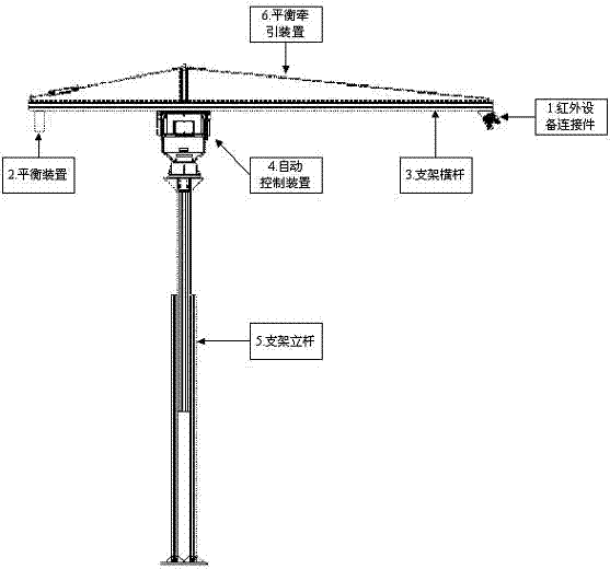
[0034] The present invention will be further described below in conjunction with the accompanying drawings and embodiments.

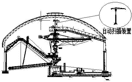
[0035] Such as figure 1 shown.

[0036] An automatic scanning device for coal yard monitoring, which includes:

[0037] A scanning device 1, the scanning device 1 is installed on the long cantilever end of the bracket cross bar 3 through a connecting piece, and the scanning device includes one of an infrared scanner, a laser scanner, an infrared thermal imager, and the like. ;

[0038] A balance fitting 2, the balance device 2 is used to counterweight the scanning device 1, which can be realized by one of counterweight block, counterweight iron, counterweight ore, counterweight iron sand, etc.;

[0039] A bracket bar 3, the two ends of the bracket bar 3 are respectively installed with a scanning device 1 and a balancer 2 and can be wired;

[0040] A rotating device 4, the rotating device 4 is used to drive the bracket cross bar 3 to rotate 360 ...


PUM

PropertyMeasurementUnit
diameteraaaaaaaaaa
tensile loadaaaaaaaaaa

Abstract

The invention discloses an automatic scanning device for monitoring a coal yard. The automatic scanning device is characterized by comprising a bracket upright rod (5), a rotating device (4) and a bracket transverse rod (3), wherein the bracket upright rod (5) is used as a support for the entire scanning device; one end of the bracket upright rod (5) is fixed to a supporting platform, and the other end of the bracket upright rod (5) is used for bearing the rotating device (4); the bracket transverse rod (3) is born on the rotating device (4) and rotates according to a set rule under the driving of the rotating device (4) to drive scanning equipment (1) mounted at one end of the bracket transverse rod (3) to scan the coal yard in all directions; data or image obtained by scanning of the scanning equipment (1) is transmitted to a monitoring room in a wired or wireless mode; and a balance weight (2) with an adjustable position is arranged at the other end of the bracket transverse rod (3). The automatic scanning device has the advantages of simplicity for construction and debugging, convenience for overhauling and maintenance, unattended operation, low operation power consumption, automatic operation, high protective level and the like. The problems such as complexity in construction, long period, high operation power consumption and multi-person cooperation existing in the original scheme are solved.

Description

technical field [0001] The invention relates to an automatic scanning device, especially a monitoring device suitable for a circular closed coal storage yard or a transfer station that needs to be monitored at a high altitude and in a full range, specifically an automatic scanning device for coal yard monitoring. device. Background technique [0002] As we all know, coal, as an important industrial raw material and fuel, plays an important role in power generation, smelting, chemical industry, building materials and other industries. As a non-renewable resource, how to rationally and effectively develop, store, and transport coal resources to reduce unnecessary waste will be the direction we need to work hard. After coal has been transported and stored for a long time, it is prone to spontaneous combustion due to factors such as moisture volatilization and changes in compaction. If the loss of a larger area is caused, the installation of temperature monitoring equipment on...

Claims


Application Information

Patent Timeline
Patent Type & Authority Patents(China)
IPC IPC(8): G01J5/02G01K1/00
Inventor 陈家庆黄进姜坤吉锋
Owner 南京卓越能源技术有限公司
Learn More