
Measurement device for thermal shrinkage ratio of pull wire

A measuring device and technology of thermal shrinkage rate, applied in the direction of material thermal expansion coefficient, etc., can solve problems such as difficult to accurately measure size, easy to wrinkle, twist, narrow width, etc., to avoid heat loss, fast action, and high degree of automation Effect

Active Publication Date: 2012-08-01
CHINA TOBACCO GUANGDONG IND +2
View PDF7 Cites 12 Cited by
  • Summary
  • Abstract
  • Description
  • Claims
  • Application Information

AI Technical Summary

Problems solved by technology

[0004] At the same time, there are also some problems in the actual test process of the heat shrinkage rate of the drawn wire, because the standard is mainly aimed at the film used for cigarette packaging, and the drawn wire has its own characteristics, its width is very narrow, and it is relatively soft. It is easy to wrinkle and twist during the process, and the deformation is serious, so it is difficult to measure the size accurately

Method used


Image

  • Measurement device for thermal shrinkage ratio of pull wire
  • Measurement device for thermal shrinkage ratio of pull wire
  • Measurement device for thermal shrinkage ratio of pull wire

Examples


Embodiment 1

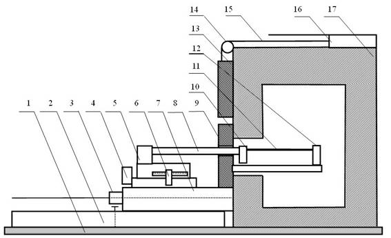
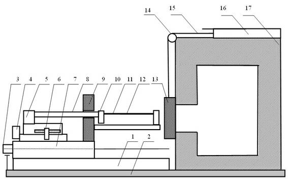
[0039] Such as figure 1 As shown, a measuring device for the heat shrinkage rate of a cable includes a measuring unit, an oven movable door lifting unit and an oven. The measuring unit includes a guide rail 2, a rodless cylinder 3, an electric platform 4, a tension sensor 5, a displacement sensor 6, and a fixed plate 7. Connecting rod 8, oven fixed door 9, left fixture 10 and right fixture 12;

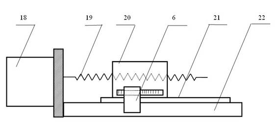
[0040] Electric platform 4 reference image 3 Set up, comprise stepping motor 18, platform fixed block 22, platform moving block 20, leading screw 19 and precision guide rail 21, stepping motor 18 is fixed on the platform fixing block 22, drives platform moving block 20 by leading screw 19 in precision Slide on the guide rail 21;

[0041] The fixed plate 7 is fixed on the slider of the rodless cylinder 3, the platform fixed block 22 and the oven fixed door 9 are fixed on the fixed plate 7, the guide rail 2 is fixed on the bottom of the fixed plate 7, both sides of the rodless cylinde...

Embodiment 2

[0048] The device constructed in Example 1 was used to perform the heat shrinkage test of the drawn wire.

[0049] First, the oven movable door 13 seals the oven door hole, and the oven temperature rises to a set value. Clamp one end of the pull wire 11 on the right clamp 12, and clamp the other end on the left clamp 10. At this time, the initial distance of the system is L 0 (Theoretically, this position is 100mm according to the industry standard). The electric platform 4 moves away from the clamp to make the pull wire 11 subject to tension. When the measured value of the tension sensor 5 reaches the specified value, the displacement sensor 6 records the displacement L of the electric platform 4 1 , calculate the original length L=L of the guy wire 11 0 + L 1 .

[0050] Then the electric platform 4 drives the left clamp 10 to move a certain distance towards the direction close to the clamp, so that the stay wire 11 is in a relaxed state. The air cylinder 16 is connected...


PUM


Abstract

The invention discloses a measurement device for the thermal shrinkage ratio of a pull wire. The principle of measurement is as follows: properly tightening the pull wire through an electric platform, recording the original length L of the pull wire through a displacement sensor, moving the electric platform to enable the pull wire to be in a relaxed state, placing the pull wire into an oven, heating for a while, taking out the pull wire, cooling to a testing ambient temperature, moving the electric platform to tighten the pull wire to a same degree, recording the length of the pull wire through the displacement sensor, and calculating the thermal shrinkage ratio of the pull wire according to a thermal shrinkage ratio calculation formula epsilon=(L-S) / L*100%. The measurement device disclosed by the invention realizes the automatic measurement of the thermal shrinkage ratio of the pull wire by the steps of driving the pull wire to move through the electric platform, measuring the tensile force born by the pull wire using a tension sensor, and measuring the length change of the pull wire through the displacement sensor.

Description

Technical field [0001] The present invention involves the field of cigarette pull line detection technology, and the measurement device that specifically involves the heat contraction rate of the line. Background technique [0002] The cigarette pull line is not only a tool to help consumers open the cigarette outsourcing film, but also one of the important means of anti -counterfeiting of cigarette companies.According to statistics, more than 90%of cigarettes in thin film outsourcing are used.The performance of the pull line, especially the characteristics of heating contraction, has an important impact on the aesthetics of the cigarette outsourcing film. The appropriate thermal contraction rate can make cigarette outsourcing more tight and evenly uniform wrapping, avoiding the problem of incompleteness of folds and packaging of packaging cover. [0003] The essence of the pull line is a film with pressure -sensitive glue. Its thermal contraction test method is similar to the th...

Claims


Application Information

Patent Timeline
IPC IPC(8): G01N25/16
Inventor 李旭华李志刚方细玲张龙刘丹苗芊叶长文谢定海张勍
Owner CHINA TOBACCO GUANGDONG IND
Learn More