Pilot protection method based on signal distance and n-type circuit model

A line model and longitudinal protection technology, applied in the direction of fault location, etc., can solve the problems of reliability dependence of criterion, poor setting of setting value, incorrect action of protection, etc.

Inactive Publication Date: 2012-08-01
KUNMING UNIV OF SCI & TECH
View PDF6 Cites 13 Cited by
  • Summary
  • Abstract
  • Description
  • Claims
  • Application Information

AI Technical Summary

Problems solved by technology

However, traditional longitudinal protection such as optical fiber current differential and high-frequency protection is affected by the distributed capacitance of ultra-high voltage long lines, the difference in transient characteristics and saturation of TA on both sides, and the communication channel, which may easily cause incorrect protection actions
In a transmission line equipped with a wave trap, the fault identification criteria for internal and external faults composed of different high-frequency content are used. Since the reliability of the criterion depends on the characteristics of the physical boundary frequency, there will be problems in setting the setting value in practical applications. The problem

Method used


Image

  • Pilot protection method based on signal distance and n-type circuit model
  • Pilot protection method based on signal distance and n-type circuit model
  • Pilot protection method based on signal distance and n-type circuit model

Examples


Embodiment 1

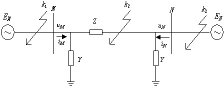
[0046] Embodiment 1: Simulation system such as figure 1 As shown, the transmission line M-N adopts the J.Marti frequency-dependent line model, and the total length of the line is 150km. The total capacitance of the line α-mode is 2.1324e-6F, the line α-mode resistance R=2.8143e-005Ω / m, the line α-mode capacitance C= 1.4215e-05uF / m, the line α-mode inductance L=8.0223e-007 H / m . A single-phase ground fault occurs outside the M-N reverse zone of the line, and the fault location is 40km away from the M terminal, such as figure 1 middle k 1 , Transition resistance 100 ohms.

[0047] When the transmission line fails, the simulated sampling frequency is set to 20kHz, and within a short time window of 3ms, the voltages at points M and N at the protective installations at both ends of the transmission line are measured u M 、u N and current i M 、i N , by analyzing the concentrated parameter Π-type equivalent circuit of the transmission line, according to Kirchhoff's current...

Embodiment 2

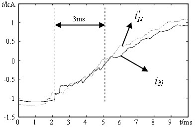
[0059] Embodiment 2: Simulation system such as figure 1 As shown, the transmission line M-N adopts the J.Marti frequency-dependent line model, and the line parameters are the same as those in Embodiment 1. A phase-to-ground fault occurs in the M-N area of ​​the line, and the fault location is 10km away from the M terminal. figure 1 middle k 2 , Transition resistance 10 ohms.

[0060] After the transmission line fails, take the simulation sampling frequency as 20kHz, and within the short time window of 3ms, follow the same method as in Embodiment 1 to simulate and calculate the end of the transmission line ( N side) current . Current measured at point N at the end of the line i N with analog current waveform like image 3 shown.

[0061] Take the tuning factor k a =0.6, set the setting value is 0.35. After calculation, within the time window of 3ms, the analog current and measured current i N Mutual distance =0.986,

[0062] > , it is judged as a fau...

Embodiment 3

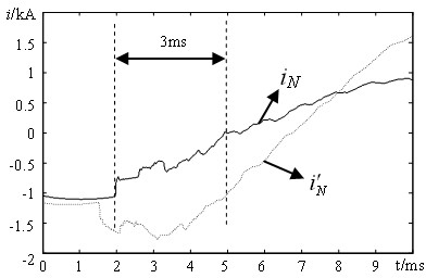
[0063] Embodiment 3: simulation system such as figure 1 As shown, the transmission line M-N adopts the J.Marti frequency-dependent line model, and the line parameters are the same as those in Embodiment 1. A phase-to-earth fault occurs outside the forward direction of line M-N, and the fault location is 70km away from the N terminal. figure 1 middle k 3 , Transition resistance 100 ohms.

[0064] After the transmission line fails, the simulation sampling frequency is set to 20kHz, and within a short time window of 3 ms, the current at the end (N side) of the transmission line is simulated and calculated according to the same method as in Example 1 .

[0065] Take the tuning factor k a =0.6, set the setting value is 0.35. After calculation, within the time window of 3ms, the analog current and measured current i N Mutual distance =0.145, ≤ , it is judged as an out-of-area fault of the transmission line.


PUM


Abstract

The invention relates to a pilot protection method based on a signal distance and an n-type circuit model, and belongs to the technical field of electric transmission line relay protection. The pilot protection method comprises the following steps of: when an electric transmission line fails, measuring the voltages uM and uN and the currents iM and iN of an M point and an N point of protection mounting places at two ends of the electric transmission line in a short time window; obtaining an expression of the analog current of the N point at the tail end of the electric transmission line according to a Kirchhoff's current theorem by analyzing a concentration parameter n-type equivalent circuit of the electric transmission line; performing analog calculation of the current of the N point of the electric transmission line by using the actually-measured voltage uM and the actually-measured current iM of the M point at the head end of the electric transmission line; calculating the mutual distance degree of the analog current and the actually-measured current iN by comparing waveforms of the analog current and the actually-measured current iN of the N point at the tail end of the electric transmission line; and comparing the calculated mutual distance degree with a set mutual distance degree setting value, and identifying internal and external faults of an area according to the relation between the calculated mutual distance degree and the set mutual distance degree setting value. The pilot protection method has the advantages of quickly and reliably identifying the internal and external faults of the area, being not influenced by excessive resistance and fault initial angles, and the like.

Description

technical field [0001] The invention relates to a longitudinal protection method based on a signal distance and a Π-type line model, and belongs to the technical field of electric power system relay protection. Background technique [0002] The longitudinal protection can realize full-line quick action and has absolute selectivity, so it can meet the needs of power system stability and fully meet the requirements of selectivity, sensitivity, quick action and reliability of relay protection. However, traditional longitudinal protection, such as optical fiber current differential and high-frequency protection, is affected by the distributed capacitance of the ultra-high voltage long line, the difference in the transient characteristics and saturation degree of TA on both sides, and the communication channel, which may easily cause incorrect action of the protection. In a transmission line equipped with a wave trap, the fault identification criteria for internal and external fa...

Claims


Application Information

Patent Timeline
Patent Type & Authority Applications(China)
IPC IPC(8): G01R31/08
Inventor 束洪春蒋彪董俊田鑫萃
Owner KUNMING UNIV OF SCI & TECH
Why Eureka
Try Eureka