
Data truncation method in radar signal processor

A radar signal and processor technology, applied in the field of data interception, can solve the problems of low degree of automation, low precision, slow response time, etc., and achieve the effect of high degree of automation

Inactive Publication Date: 2012-08-01
XIDIAN UNIV
View PDF2 Cites 2 Cited by
  • Summary
  • Abstract
  • Description
  • Claims
  • Application Information

AI Technical Summary

Problems solved by technology

Different data truncation methods lead to different accuracy of the radar system, which leads to differences in the resolution of the radar signal processor
[0004] At present, there are two kinds of operations widely used in data truncation operations. One is to perform data truncation according to the value of echo data and manual experience. This data truncation method will cause low automation and slow response time of the system. And it is easy to have loopholes and then affect the work of the radar system, causing false alarms and false alarms; another method is to directly intercept the high bits of the data, such as the data truncation method mentioned in the paper "Achievement of Digital Pulse Compression System Based on FPGA" is Using the method of intercepting high bits, this method makes the effective bits of the data not fully utilized, resulting in low precision

Method used


Image

  • Data truncation method in radar signal processor
  • Data truncation method in radar signal processor
  • Data truncation method in radar signal processor

Examples


Embodiment 1

[0026] In Embodiment 1, the 42-bit input data D is truncated into 16-bit output data.

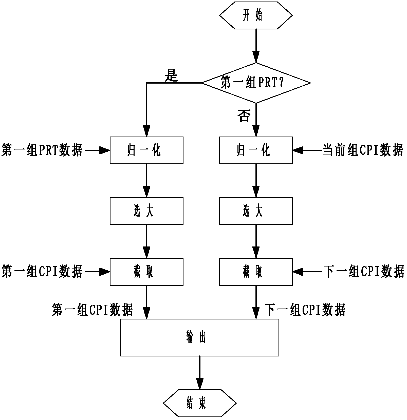
[0027] Step 1: Normalize the input data D. If the input data D is negative, the normalized data T is equal to the opposite of the input data D. If the input data D is positive or zero, then the normalized The data T is equal to the input data D itself, where the input data D is 42-bit data.

[0028] Step 2: Perform a logical OR operation on the normalized data T:

[0029] If the normalized data T belongs to the first group of pulse repetition period PRT, perform a logical OR operation on all the data in the pulse repetition period PRT to obtain the logical OR result B1 of all the data in the pulse repetition period PRT;

[0030] If the normalized data T belongs to the data in the coherent repetition interval CPI, that is, the data in the 64 sets of pulse repetition period PRT, the data in the coherent repetition interval CPI does not include the data in the first set of pulse repetition period PRT ...

Embodiment 2

[0043] In Embodiment 2, the 26-bit input data D is truncated into 16-bit output data.

[0044] Step 1. Normalize the input data D. If the input data D is negative, the normalized data T is equal to the opposite of the input data D. If the input data D is positive or zero, then the normalized The data T is equal to the input data D itself, where the input data D is 26-bit data;

[0045] Step 2. Perform a logical OR operation on the normalized data T:

[0046] If the normalized data T belongs to the first group of pulse repetition period PRT, perform a logical OR operation on all the data in the pulse repetition period PRT to obtain the logical OR result B1 of all the data in the pulse repetition period PRT;

[0047] If the normalized data T belongs to the data in the coherent repetition interval CPI, that is, the data in the 64 sets of pulse repetition period PRT, the data in the coherent repetition interval CPI does not include the data in the first set of pulse repetition period PRT ...


PUM


Abstract

The invention discloses a data truncation method in a radar signal processor, which mainly solves the problem that data truncation modules in pulse compression processing, moving target detection processing and data mode operation in the conventional radar signal processor have low precision. The method comprises the following steps of: normalizing input data, namely taking an absolute value of the input data; performing logic OR operation on normalization results of all data in a group of pulse repetition time (PRT) or coherent parameter intervals (CPI) to obtain a logic OR value of the group of data, and determining the highest nonzero digit position of the logic OR value; and finally, selecting bits of the next group of data according to the highest nonzero digit position. By the method, effective information of the data can be fully utilized; and compared with the traditional method, the method has the advantage of high data truncation precision and can be used for the pulse compression processing, moving target detection processing and data mode operation in radar signal processing.

Description

Technical field [0001] The invention belongs to the field of radar signal processing, and particularly relates to data truncation in a radar signal processor, and can be used for pulse compression processing, moving target detection processing and data modeling in radar signal processing. Background technique [0002] Radar uses the reflection of electromagnetic waves by the target to find the target and determine its position. The radar extracts relevant information from the echo reflected by the target, and detects the target's distance, azimuth and speed based on this information. The radar recognizes the size and shape characteristics of the target through the two parameters of range resolution and angle resolution. Among them, the range resolution is determined by the bandwidth of the radar signal. The improvement of the range resolution depends on increasing the bandwidth of the signal. Angle resolution The force is determined by the electrical size of the radar antenna. ...

Claims


Application Information

Patent Timeline
IPC IPC(8): G01S7/41
Inventor 史江一田映辉邸志雄杨哲马晓华马佩军郝跃闵俊红苏涛
Owner XIDIAN UNIV
Learn More