Motion slider, hammer and link mechanism of optical fiber fusion splicer

A technology of optical fiber fusion splicer and linkage mechanism, which is applied in the field of optical fiber fusion, can solve the problems of complex fusion steps, high processing cost, and low efficiency, and achieve the effects of low cost, improved work efficiency, and reduced operating procedures

Inactive Publication Date: 2012-08-01
新乡市大成科技中介服务有限公司
View PDF2 Cites 3 Cited by
  • Summary
  • Abstract
  • Description
  • Claims
  • Application Information

AI Technical Summary

Problems solved by technology

[0007] In view of the above-mentioned prior art, the technical problem to be solved by the present invention is: when the existing optical fiber fusion splicer fuses the optical fiber, a special optical fiber cutter must be used to cut the optical fiber in advance, and then the cut optical fiber is placed in the optical fiber fusion splicer for fusion splicing, so the processing High cost, complex welding steps and low efficiency

Method used


Image

  • Motion slider, hammer and link mechanism of optical fiber fusion splicer
  • Motion slider, hammer and link mechanism of optical fiber fusion splicer
  • Motion slider, hammer and link mechanism of optical fiber fusion splicer

Examples


Embodiment Construction

[0020] The present invention will be further described below in conjunction with the accompanying drawings and specific embodiments.

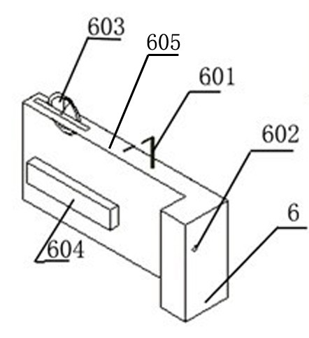
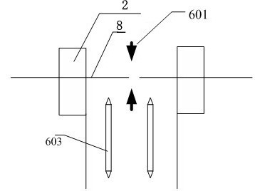
[0021] A moving slider, hammer and interlocking mechanism of an optical fiber fusion splicer, characterized in that an optical fiber cutting blade 603, a discharge electrode 601, and a stroke control mechanism are arranged on the moving slider 6; the interlocking mechanism 5 includes positioning slots, springs and The state control slider is installed on the motion slider; the stroke control mechanism determines the position of the optical fiber cutting blade, and the hammer breaks the scratched optical fiber driven by the linkage mechanism.

[0022] Such as figure 1 As shown, a protruding structure 604 is provided on the side of the moving slider to make the moving slider move stably in the sliding cavity of the frame. The moving slider is processed as a metal piece; the positioning pin 602 for determining the discharge electrode and its posi...


PUM


Abstract

The invention discloses a motion slider, a hammer and a link mechanism of an optical fiber fusion splicer, belongs to the technical field of optical fiber fusion, and is matched with an optical fiber positioning assembly. A specific optical fiber cleaver need not be used for preparing an optical fiber end surface. The optical fiber cleaving can be finished by directly pushing the motion slider in place to enable the optical fiber end surface to meet the fusion requirement and prepare for discharging fusion. The optical fiber cleaving procedure is finished on the mainframe so that the operation is simple, the history that fusion splicers have to be configured with cleavers is ended, the operation procedure is reduced, the fusion time is shortened, the requirement for an operation room is lowered, the working efficiency is improved, and single operation is really achieved.

Description

technical field [0001] The invention relates to the technical field of optical fiber fusion splicing, in particular to a moving slider, hammer and linkage mechanism of an optical fiber fusion splicing machine. Background technique [0002] Optical fiber fusion splicer is a kind of communication engineering equipment that melts the two ends of the optical fiber by the high temperature formed by the discharge of the arc, and at the same time uses the collimation principle to advance gently to realize the coupling of the optical fiber mode field. It is widely used in communication engineering construction, maintenance, and communication equipment production. in manufacture. In the 1970s, the first optical fiber fusion splicing machine was born in Siemens, Germany. At that time, acetylene flame fusion was used, and it gradually developed to rely on a microscope to observe the fiber splicing end face (end face after cutting) in three-dimensional space (X, Y, Z axis) The position...

Claims


Application Information

Patent Timeline
Patent Type & Authority Applications(China)
IPC IPC(8): G02B6/255G02B6/25
Inventor 李亮
Owner 新乡市大成科技中介服务有限公司
Why Eureka
Try Eureka