
Substation area control method and system of microgrid operation mode

A technology of operation mode and control method, applied in the field of electric power, can solve the problems of low degree of automation, inability to ensure continuous and reliable operation of microgrids, inability to facilitate information sharing between devices, etc., and achieve the effect of convenient operation and maintenance

Active Publication Date: 2014-05-28
ZHUHAI POWER SUPPLY BUREAU GUANGDONG POWER GIRD CO
View PDF3 Cites 0 Cited by
  • Summary
  • Abstract
  • Description
  • Claims
  • Application Information

AI Technical Summary

Problems solved by technology

Because the traditional microgrid control technology cannot control the load capacity, if the load capacity is greater than the microsource capacity during the island operation, the microsource in the island operation system will be forced to stop running, and the continuous and reliable operation of the microgrid in the island mode cannot be guaranteed.
[0003] The conversion between the grid-connected operation mode and the island operation mode of the traditional microgrid is realized by judging local parameters, and information sharing between devices cannot be conveniently realized, and the degree of automation is low

Method used


Image

  • Substation area control method and system of microgrid operation mode
  • Substation area control method and system of microgrid operation mode
  • Substation area control method and system of microgrid operation mode

Examples


Embodiment

[0022] The present invention is based on network and IEC61850 standards to collect real-time operation information of relevant parts of the grid-connected power generation system in the substation area, perform centralized judgment and calculation, and realize automatic conversion between the station-level grid-connected operation mode and the micro-grid operation mode.

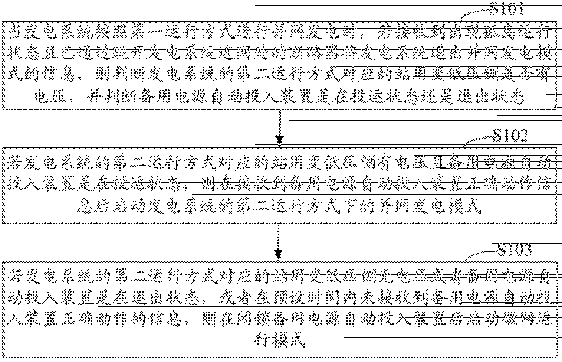
[0023] see figure 1 As shown in FIG. 2 , it is a flow chart of the station domain control method in the operation mode of the microgrid according to the embodiment of the present invention. Such as figure 1 As shown, the station domain control method of the microgrid operation mode in this embodiment includes:

[0024] Step S101: When the power generation system is performing grid-connected power generation according to the first operation mode, if it receives the information that the island operation state occurs and the power generation system has exited the grid-connected power generation mode by jumping ...

Embodiment 2

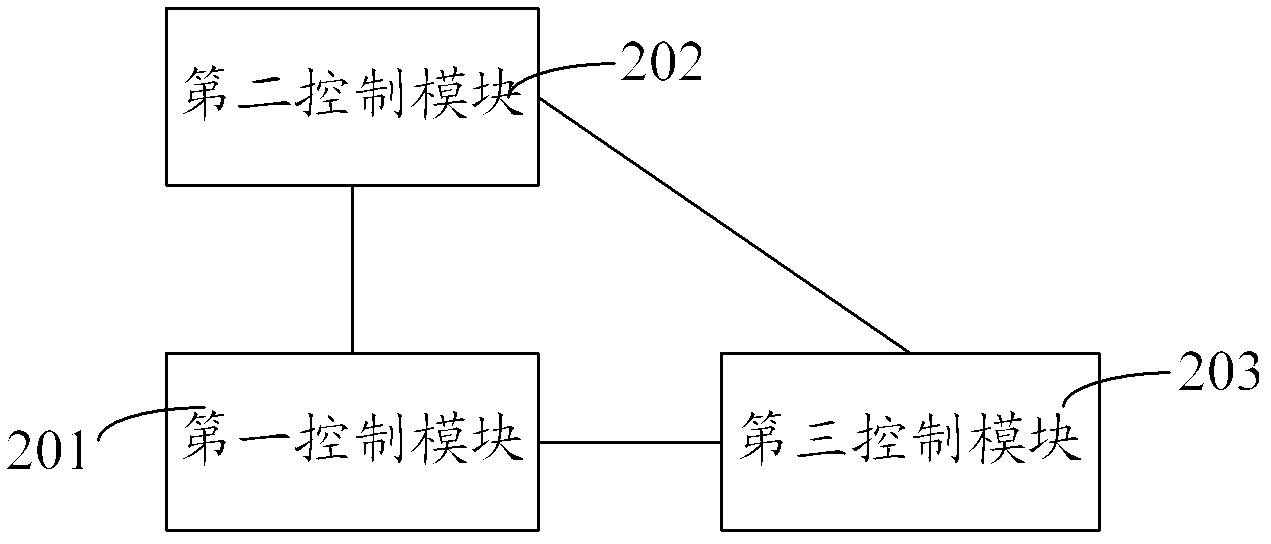
[0038] According to the station domain control method of the microgrid operation mode of the present invention, the present invention also provides a station domain control system of the micro grid operation mode. The station domain control system of the micro grid operation mode of this embodiment is based on the network and the IEC61850 standard Collect real-time operation information related to the grid-connected power generation system in the substation area, perform centralized judgment and calculation, and realize automatic conversion between the station-level grid-connected operation mode and the micro-grid operation mode. An embodiment of the station domain control of the microgrid operation mode of the present invention will be described in detail below.

[0039] figure 2 shows a schematic structural diagram of a station domain control system in a microgrid operation mode according to an embodiment of the present invention, which includes a first control module 201, ...

Embodiment 3

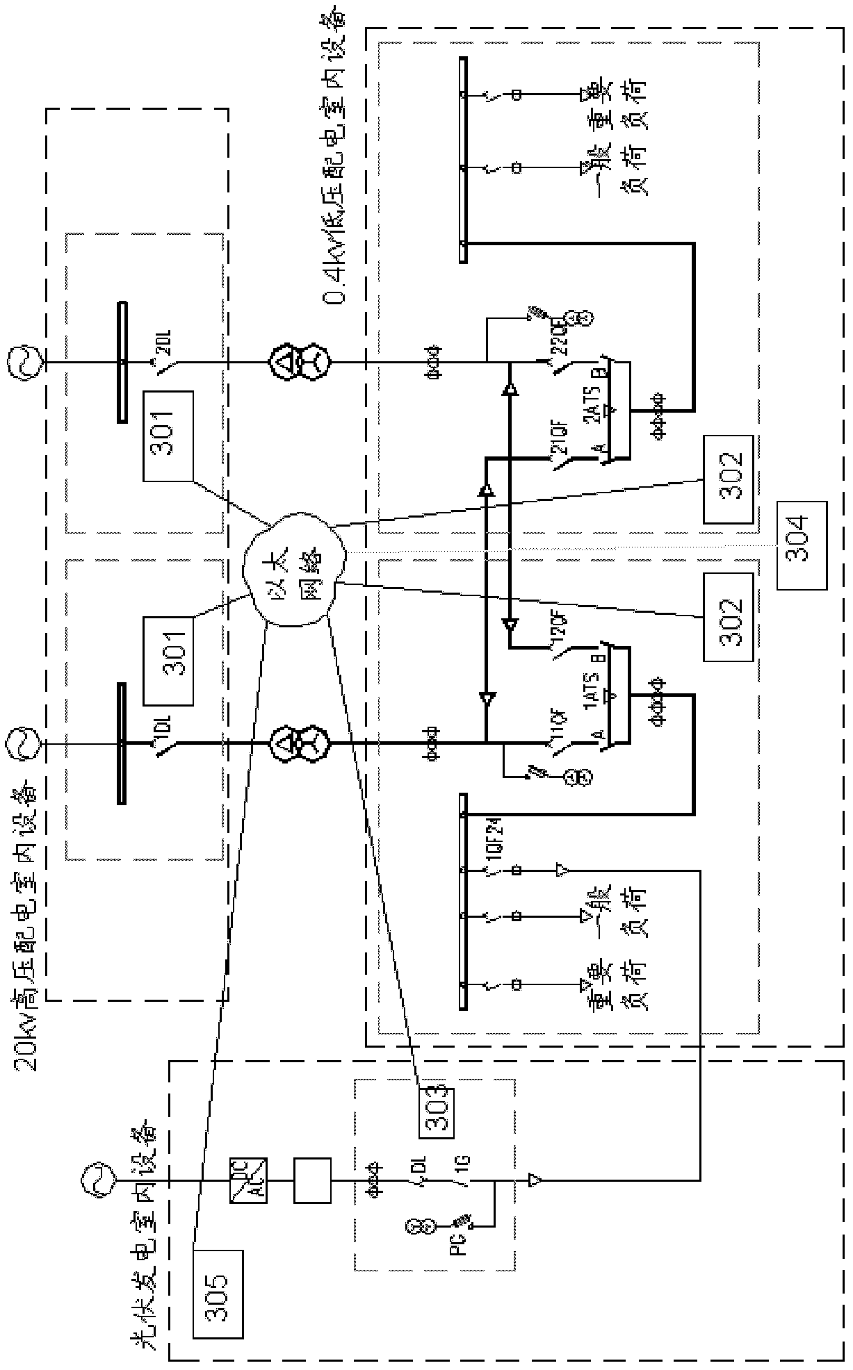
[0051] In order to facilitate the understanding of the present invention, this embodiment uses a specific example to describe the present invention in detail, but this specific example does not limit the patent scope of the present invention. This embodiment takes the microgrid operation mode control method of a photovoltaic power station as an example, see image 3 As shown, it is a layout diagram of relevant equipment of the microgrid operation mode control system in the photovoltaic power station domain in this embodiment.

[0052] Such as image 3 Shown: When the photovoltaic power generation system generates power in the following operating state, that is, the DL circuit breaker in the photovoltaic room is in the closed position, and the 1G is in the closed position; The 11QF circuit breaker is in the closed position; the 1DL circuit breaker connected to the power system in the 20kV high-voltage power distribution room is in the closed position. We call the photovoltaic ...


PUM


Abstract

The invention relates to a substation area control method and system of a microgrid operation mode. The substation area control method comprises the following steps of: when a power generation system is subjected to grid-connected power generation according to a first operation mode, if an island operation state appears and a grid-connected power generation mode exits, judging whether the low voltage side of a transformer for a substation corresponding to a second operation mode of the power generation system has voltage, judging which state automatic throw-in equipment of emergency power supply is; if the low voltage side has voltage and is in a commissioning state, receiving correct action formation of the automatic throw-in equipment of emergency power supply and starting the second operation mode; and if the low voltage side does not have voltage or the automatic throw-in equipment of emergency power supply is in an exit state, or the correct action information of the automatic throw-in equipment of emergency power supply is not received within preset time, locking the automatic throw-in equipment of emergency power supply and then starting the microgrid operation mode. According to the substation area control method and system, concentrated judgment and computation are carried out by acquiring real-time operation information of parts in the substation transformer area, which are related to the power generation system, and effective control based on the substation-grid microgrid operation mode is achieved.

Description

technical field [0001] The invention relates to the field of electric power technology, in particular to a station domain control method and system of a microgrid operation mode. Background technique [0002] The power source in the microgrid is called a microsource, and the microgrid can run in parallel with the power system or in an island. Regardless of the operating mode, it is necessary to effectively control the micro-source to maintain the stability of the system voltage and frequency. During grid-connected operation, the power system provides voltage support, each micro-source adopts output power control mode, and the micro-source is regarded as a schedulable and controllable current source. During island operation, each micro-source is required to automatically adjust power output following load changes, and at the same time meet the output voltage and frequency changes within the allowable range, which requires the micro-source to have a certain power generation c...

Claims


Application Information

Patent Timeline
Patent Type & Authority Patents(China)
IPC IPC(8): H02J3/00H02J3/38H02J9/06
CPCY02B70/30Y02P80/14Y04S20/20
Inventor 邹国惠翁奕珊孙玉彤胡云花罗奕飞张桂娟何文吉鲁明佳代卫星
Owner ZHUHAI POWER SUPPLY BUREAU GUANGDONG POWER GIRD CO
Learn More