
Fuel injection valve

A technology of fuel injection valve and fuel, which is applied in the direction of fuel injection devices, charging systems, engine components, etc., and can solve problems such as valve needle deflection

Inactive Publication Date: 2012-08-01
ROBERT BOSCH GMBH
View PDF14 Cites 1 Cited by
  • Summary
  • Abstract
  • Description
  • Claims
  • Application Information

AI Technical Summary

Problems solved by technology

In addition, the larger opening angle of the valve seat reduces disturbing forces on the valve needle due to the fluid, which may lead to misalignment of the valve needle

Method used


Image

  • Fuel injection valve
  • Fuel injection valve
  • Fuel injection valve

Examples


Embodiment Construction

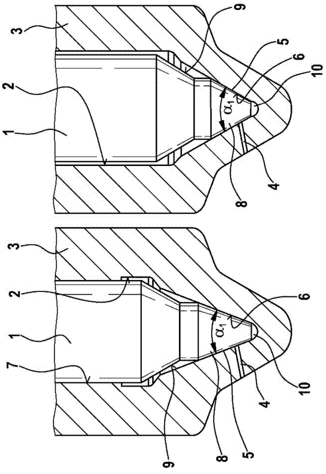
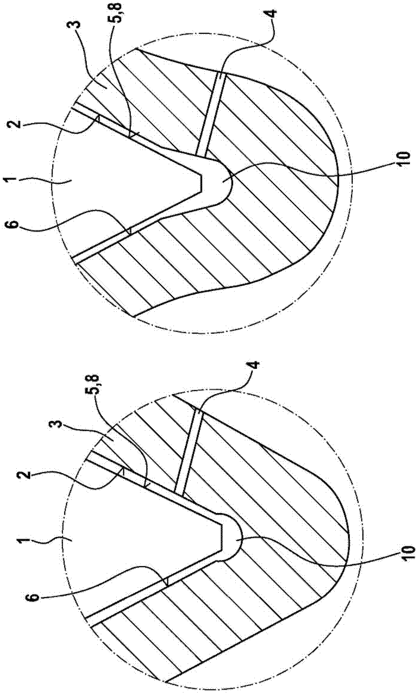
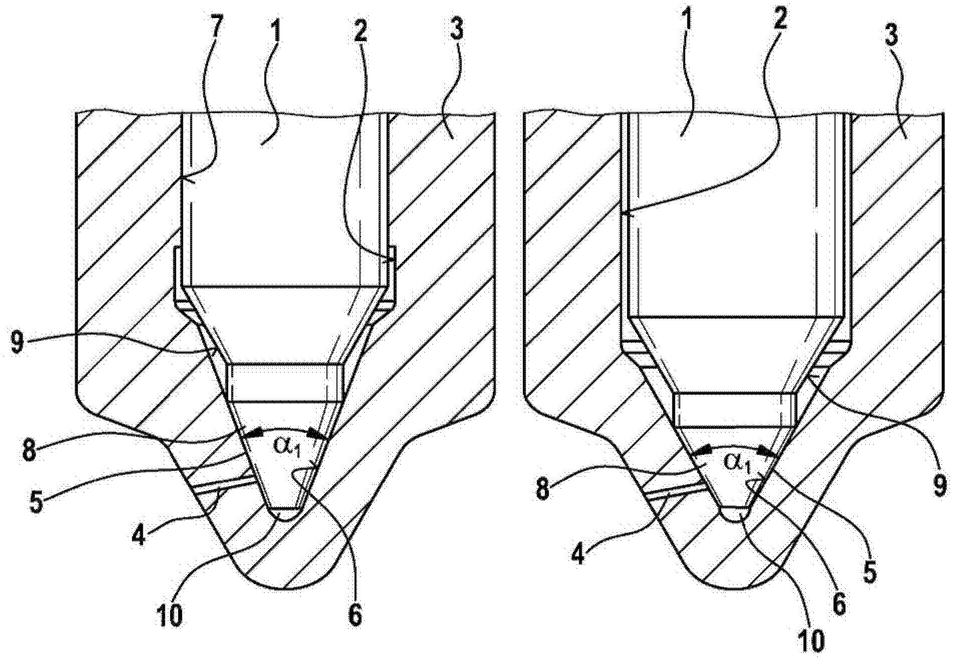
[0018] figure 1 For comparison, a nozzle structure according to the invention is shown on the left and a known nozzle structure is shown on the right. The two nozzle structures comprise a nozzle needle 1 which is guided reciprocatingly in a central bore 2 of a nozzle body 3 . For this purpose, the nozzle structure according to the invention has a guide point 7 close to the sealing surface, which has a reduced diameter. At least one spray opening 4 is released or closed by the reciprocating movement of the nozzle needle 1 . The two nozzles are configured as matching hole nozzles, ie at least one spray hole 4 opens into the central bore 2 at a sealing surface 6 formed within the central bore 2 . The sealing surfaces 6 each have a conical course which substantially corresponds to the conically extending sub-region 8 of the nozzle needle 1 and forms the sealing point 5 . The cylindrical subsection and then the conical subsection adjoin the conical subsection 8 of the nozzle nee...


PUM


Abstract

The invention relates to a fuel injection valve for injecting fuel into a combustion chamber of an internal combustion engine, having a nozzle needle (1) which is guided, such that it can perform a stroke movement, in a central bore (2) of a nozzle body (3) in order to open up or close off at least one injection opening (4), wherein the nozzle needle (1) interacts, by means of an encircling sealing region (5) formed on the combustion-chamber-side end thereof, with a sealing seat (6) that runs conically and is formed on the combustion-chamber-side end of the nozzle body (3). According to the invention, the sealing seat (6) that runs conically has an opening angle ([alpha]1) of between 30 DEG and 50 DEG , preferably of between 40 DEG and 50 DEG .

Description

technical field [0001] The invention relates to a fuel injector having the features of the preamble of claim 1 for injecting fuel into a combustion chamber of an internal combustion engine. Background technique [0002] Laid-open document DE 10 2006 012 242 A1 discloses a fuel injection valve for an internal combustion engine which has a valve body in which a pressure chamber is formed which is filled with fuel under high pressure and from which at least one injection opening originates. A longitudinally displaceable valve needle is arranged in the pressure chamber, which interacts via a sealing surface with a conical valve seat formed in the pressure chamber for opening and closing the at least one injection opening. In order for sufficient fuel to flow between the valve needle sealing surface and the valve seat to the injection opening for achieving the corresponding injection rate, the valve needle must be moved by a defined minimum travel. Because this point has to be o...

Claims


Application Information

Patent Timeline
Patent Type & Authority Applications(China)
IPC IPC(8): F02M61/12F02M61/18F02M61/10
CPCF02M61/1886F02M61/12F02M61/18F02M61/10
Inventor M·洛伊卡特K·格罗特W·克里斯特G·辛德豪夫
Owner ROBERT BOSCH GMBH
Learn More