Clamping mechanism of pipe cutting machine
A technology of clamping mechanism and pipe cutting machine, which is used in clamping, metal sawing equipment, metal processing machinery parts, etc., can solve the problem of saw blade jitter, beating, increased linear speed, large space requirements, and difficulty in ensuring smooth cuts Smoothness and other problems, to achieve the effect of smooth and smooth material incision and small beating
- Summary
- Abstract
- Description
- Claims
- Application Information
AI Technical Summary
Problems solved by technology
Method used
Image
Examples
Embodiment 1
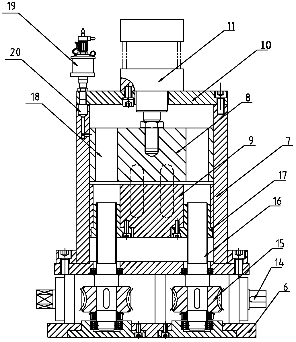
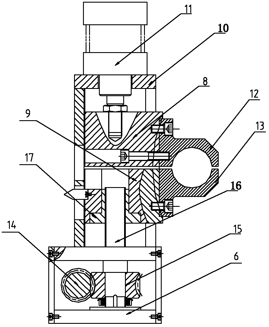
[0025] Example 1 is as Figure 2-3 As shown, the clamping mechanism of the pipe cutting machine includes a base 6, a plurality of side plates 7 are arranged on the base 6, an upper slider 8 and a lower slider 9 are movably arranged in the side plate 7, and a top plate 10 is arranged on the side plate 7. , the top plate 10 is provided with a slider drive mechanism 11, the upper slider 8 is provided with an upper clamping block 12 on the side, the lower slider 9 is provided with a lower clamping block 13 on the side, and the upper slider 8 and the slider drive The mechanism 11 is connected, and the base 6 is provided with an adjustment mechanism for synchronously adjusting the two sides of the lower slider 9 .
[0026] The adjustment mechanism includes a worm 14 arranged in the base 6, and two worm wheels 15 matched with the worm 14. The end of the main shaft of the worm wheel 15 is provided with a lead screw 16, and the lower slider 9 is provided with two adjustment holes. , t...
Embodiment 2
[0027] Example 2 is as Figure 4-5 As shown, the clamping mechanism of the pipe cutting machine includes a base 6, a plurality of side plates 7 are arranged on the base 6, an upper slider 8 and a lower slider 9 are movably arranged in the side plate 7, and a top plate 10 is arranged on the side plate 7. , the top plate 10 is provided with a slider drive mechanism 11, the upper slider 8 is provided with an upper clamping block 12 on the side, the lower slider 9 is provided with a lower clamping block 13 on the side, and the upper slider 8 and the slider drive The mechanism 11 is connected, and the base 6 is provided with an adjustment mechanism for synchronously adjusting the two sides of the lower slider 9 .
[0028] The adjustment mechanism includes a driving gear 21 arranged in the base 6, and a driven gear 22 that is arranged on both sides of the driving gear 21 and matched with the driving gear 21. The main shaft end of the driven gear 22 is provided with a lead screw 16, ...
Embodiment 3
[0029] Example 3 is as Figure 6-7 As shown, the clamping mechanism of the pipe cutting machine includes a base 6, a plurality of side plates 7 are arranged on the base 6, an upper slider 8 and a lower slider 9 are movably arranged in the side plate 7, and a top plate 10 is arranged on the side plate 7. , the top plate 10 is provided with a slider drive mechanism 11, the upper slider 8 is provided with an upper clamping block 12 on the side, the lower slider 9 is provided with a lower clamping block 13 on the side, and the upper slider 8 and the slider drive The mechanism 11 is connected, and the base 6 is provided with an adjustment mechanism for synchronously adjusting both sides of the lower slider 9 .
[0030] The adjustment mechanism includes a rack 23 arranged in the base 6, and two gears 24 matched with the rack 23. The end of the main shaft of the gear 24 is provided with a lead screw 16, and the lower slider 9 is provided with two gears 24. The adjustment hole is pro...
PUM
 Abstract
Description
Claims
Application Information
 - R&D
- Intellectual Property
- Life Sciences
- Materials
- Tech Scout
- Unparalleled Data Quality
- Higher Quality Content
- 60% Fewer Hallucinations
Browse by: Latest US Patents, China's latest patents, Technical Efficacy Thesaurus, Application Domain, Technology Topic, Popular Technical Reports.
© 2025 PatSnap. All rights reserved.Legal|Privacy policy|Modern Slavery Act Transparency Statement|Sitemap|About US| Contact US: help@patsnap.com


