Method for registering camera spindle and laser beam in parallel

A laser beam and camera technology, applied in the field of computer vision, can solve problems such as the difficulty in parallel registration of the main axis of the camera and the laser beam, measurement accuracy discount, not the same target (or the same position of the target, etc.), and the calibration speed is fast and easy to implement , high-precision effect

Inactive Publication Date: 2012-08-08
CHINESE AERONAUTICAL RADIO ELECTRONICS RES INST
View PDF4 Cites 10 Cited by
  • Summary
  • Abstract
  • Description
  • Claims
  • Application Information

AI Technical Summary

Problems solved by technology

Therefore, parallel registration of the camera axis and laser beam is often difficult
[0004] Through the retrieval of relevant technical literature, it was found that Chao Zhichao's "Monocular Camera Laser Rangefinder Sensor Pose Measurement System" published in "Acta Optics" Volume 31 Issue 3 in March 2011 used a camera spindle and a laser rangefinder laser. However...

Method used


Image

  • Method for registering camera spindle and laser beam in parallel
  • Method for registering camera spindle and laser beam in parallel
  • Method for registering camera spindle and laser beam in parallel

Examples


Embodiment

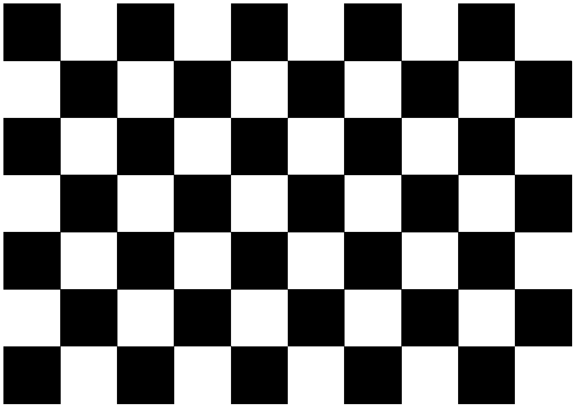
[0023] Step 1, photographing the checkerboard calibration block and the spot image formed by the laser beam on the checkerboard calibration block.

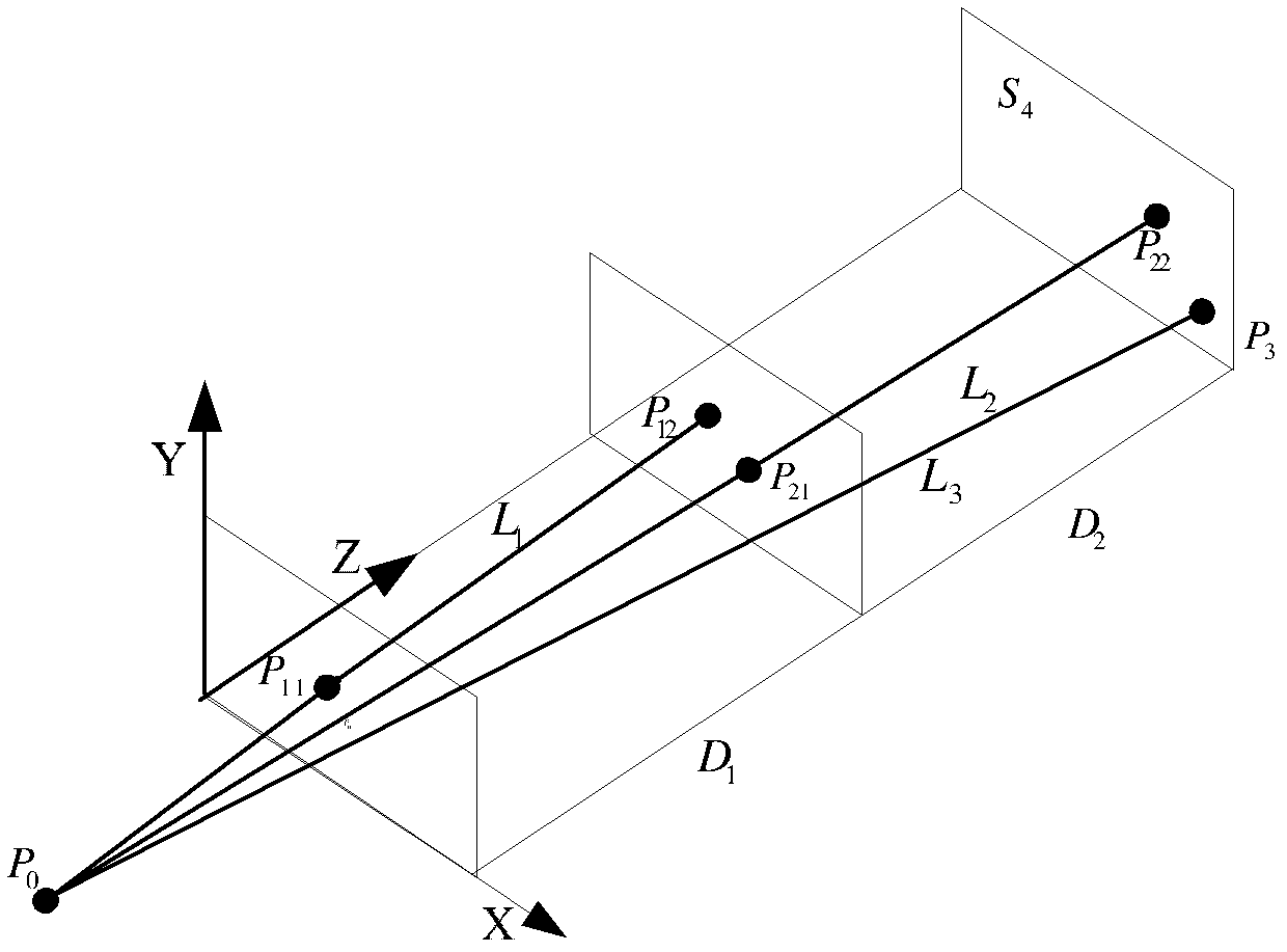
[0024] The calibration process uses figure 1 Calibration block shown. Place the calibration block in front of the camera, which is a fixed-focus camera. Such as figure 2 The world coordinate system is established as shown, in the figure X, Y, Z are the coordinate axes of the world coordinate system, and P 0 is the origin of the laser beam, S 1 is the plane where the initial position of the calibration block is located. Adjust the rotation angle of the laser transmitter so that it can irradiate on the calibration block, and the laser beam is on the calibration block (plane S 1 ) on the point of light marked as P 11 , and fix the position of the laser emitter, take the image I 1 . Translate the calibration block vertically along the Z axis for a distance D 1 , at this time the plane where the calibration block is located i...


PUM


Abstract

The invention provides a method for registering a camera spindle and a laser beam in parallel. The method can be used in a system including a camera and a laser transmitter (a laser rangefinder or a laser structure light) to register the system in parallel; namely, the placing positions of the camera and the laser transmitter are adjusted so that the camera spindle of the camera is parallel to the laser beam transmitted by the laser transmitter. The method comprises the following steps of: shooting images of a chessboard calibration block and light spots, wherein the light spots are formed by the laser beam on the chessboard calibration block; and then calibrating camera parameters (a camera matrix) by using shot images and estimating the camera spindle; next, calibrating a laser beam origin by using a plane homographic principle; and finally, estimating an image point parallel to the laser beam by using the plane homographic principle and calibrating the laser beam. By using the method for registering the camera spindle and the laser beam in parallel, provided by the invention, the calibration can be finished only by shooting four images and only one chessboard calibration block is needed for assistance; therefore, the method for registering the camera spindle and the laser beam in parallel, provided by the invention, has the advantages of high calibrating speed, easiness for realization and higher accuracy.

Description

technical field [0001] The invention relates to a method in the field of computer vision, in particular to a method for parallel registration of a camera axis and a laser beam. Background technique [0002] A sighting system that can be composed of a camera and a laser transmitter (laser rangefinder or laser structured light), which has the following functions: when the target is at the center of the camera, the laser beam is aimed at the target, or when the laser beam is aimed at the target The target is at the center of the image captured by the camera, that is, the captured target and the target indicated by the laser beam are the same target (or the same position on the target). The aiming system composed of a camera and a laser transmitter (laser rangefinder or laser structured light) is widely used in the fields of distance measurement, attitude measurement, etc., to select the target to be measured from the image captured by the camera, or to determine Take an image ...

Claims


Application Information

Patent Timeline
IPC IPC(8): G01C25/00
Inventor 翟鸣施劲松宋炜赵琦邹怡婧
Owner CHINESE AERONAUTICAL RADIO ELECTRONICS RES INST
Why Eureka
Try Eureka