Electric connector for flat conductor and method for assembling electric connector with flat conductor

An electrical connector, flat technology, applied in the field of electrical connectors, can solve the problems of complex structure of the limit device, unfavorable production efficiency, and many processes, so as to achieve convenient and fast assembly, improve production efficiency and product quality, and be easy to manufacture Effect

Inactive Publication Date: 2012-08-08
DONGGUAN YUQIU ELECTRONICS CO LTD
View PDF9 Cites 7 Cited by
  • Summary
  • Abstract
  • Description
  • Claims
  • Application Information

AI Technical Summary

Problems solved by technology

[0003] The main structure of the existing LVDS connector includes an insulating body and a shielding shell. Accommodating spaces with front and rear openings are formed in the insulating body. The aforementioned flat conductors are inserted from the rear openings of the accommodating spaces and are flattened The connecting part (gold finger) at the front end of the flat conductor is exposed at the front opening of the accommodation space; in order to prevent the flat conductor (such as FPC or FFC, etc.) Buckle into the gap to fix the flat conductor. However, the traditional LVDS connector has a complex structure of the limit device, and there are many processes when assembling the flat conductor, which is not conducive to improving production efficiency.

Method used


Image

  • Electric connector for flat conductor and method for assembling electric connector with flat conductor
  • Electric connector for flat conductor and method for assembling electric connector with flat conductor
  • Electric connector for flat conductor and method for assembling electric connector with flat conductor

Examples


Embodiment Construction

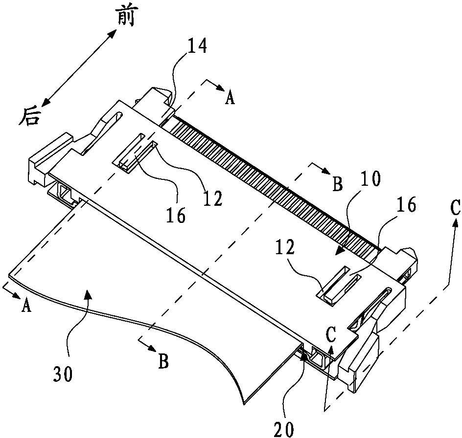
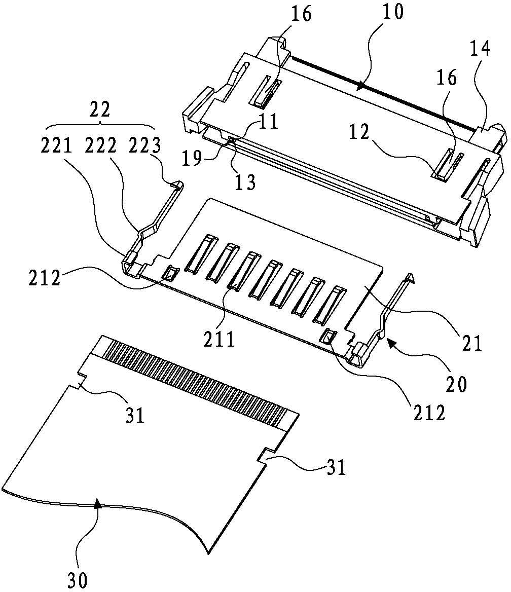
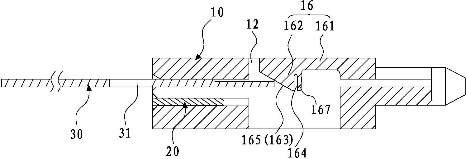
[0054] Please refer to Figure 1 to Figure 8 As shown, it shows the specific structure of the first embodiment of the present invention, including an insulating body 10 , a shielding shell 20 and a flat conductor 30 , and the flat conductor 30 is provided with two gaps 31 .

[0055] Such as figure 2 and Figure 8 As shown, the insulating body 10 has an integrated structure, and one side of the insulating body 10 is formed with an opening guide groove 11 for introducing a flat conductor 30 with a connecting portion at the front end, and the opposite side is formed with a The fitting part for connector fitting, the fitting part is provided with a fitting opening communicating with the above-mentioned guide groove 11, and the connection part on the flat conductor 30 is introduced from the open guide groove 11 and positioned in the above-mentioned fitting part to connect with the other party device contact; the rear entrance of the guide groove 11 is formed with an introduction...


PUM


Abstract

The invention discloses an electric connector for a flat conductor and a method for assembling the electric connector with the flat conductor. The electric connector comprises an insulation body and a shielding casing, wherein a guide groove for inserting the flat conductor is formed in the insulation body, two embedding grooves are arranged in positions on the insulation body corresponding to two notches of the flat conductor, the embedding grooves are communicated between the guide groove and the outer side of the insulation body in the thickness direction of the flat conductor, an elastic clamp buckle part integrally connected onto the insulation body is arranged in the embedding groove, the clamp buckle part of the elastic buckle part in the natural state extends into the guide groove, the flat conductor is inserted to prop open the elastic clamp buckle part during the assembly, after the flat conductor is completely inserted, the elastic clamp buckle part is automatically reset to buckle the flat conductor, or the clamp buckle part is firstly propped by a tool during the assembly, the tool is removed after the flat conductor is completely inserted, and the elastic clamp buckle part is automatically reset to buckle the flat conductor. The electric connector has the advantages that the structure is simple, the manufacture is easy, the assembly is convenient and fast, and the production efficiency and the product quality are effectively improved.

Description

technical field [0001] The invention relates to the technology in the field of electrical connectors, in particular to an electrical connector for a flat conductor used for liquid crystal display signal transmission and an assembly method with the flat conductor. Background technique [0002] With the vigorous development of network and communication technology, consumers have increasingly higher requirements for transmission speed. The electrical connectors used in computers and electronic products must be suitable for transmitting high-frequency and high-speed signals. Therefore, low-voltage differential signal has been developed in recent years. (Low Voltage Differential Signal, referred to as LVDS) connector, which uses extremely low voltage amplitude to transmit data at high speed, and has the advantages of low power consumption and low bit error rate. [0003] The main structure of the existing LVDS connector includes an insulating body and a shielding shell. Accommoda...

Claims


Application Information

Patent Timeline
Patent Type & Authority Applications(China)
IPC IPC(8): H01R12/61H01R13/627H01R13/648H01R43/26
CPCH01R12/774H01R13/5829Y10T29/49174H01R12/79H01R24/60H01R43/027
Inventor 万军蔡上升周亚胡光才
Owner DONGGUAN YUQIU ELECTRONICS CO LTD
Why Eureka
Try Eureka