Hand-held cutting and milling machine

A hand-held, cutting and milling technology, which is applied in the direction of milling machines, milling machine equipment, metal processing equipment, etc., can solve the problems of cutting, large depth, large volume, etc., and achieve the effect of improving work efficiency, increasing success rate, and flexible operation

Inactive Publication Date: 2012-08-15
庄永雷
View PDF10 Cites 1 Cited by
  • Summary
  • Abstract
  • Description
  • Claims
  • Application Information

AI Technical Summary

Problems solved by technology

However, the diameter of the dry cylinder liner is small, the depth is large, and the inside of the entire cylinder liner is thin and long, so there is no special cutting tool for cutting the dry type cylinder liner
At present, the cutting machines sold and used in the market are all very large and cannot be used for cutting and cutting dry cylinder liners at all.
The current smaller cutting tool, the angle grinder, cannot be used normally due to its large top and too thick handle

Method used


Image

  • Hand-held cutting and milling machine
  • Hand-held cutting and milling machine
  • Hand-held cutting and milling machine

Examples


example 1

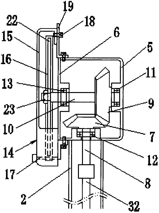
[0016] like figure 2 As shown, the gear box cover 6 is fixed on the gear box 5 with screws, the driven bevel gear 9 is horizontally installed in the gear box 5, one end of the driven gear shaft 10 is installed in the gear box sleeve 11, and the other end passes through Gear case cover is contained in case cover axle sleeve 13 lis. The driving bevel gear 7 is longitudinally installed in the gearbox 5 and meshed with the driven bevel gear 9; The outer diameter of the gear box 5 is less than 50 mm.

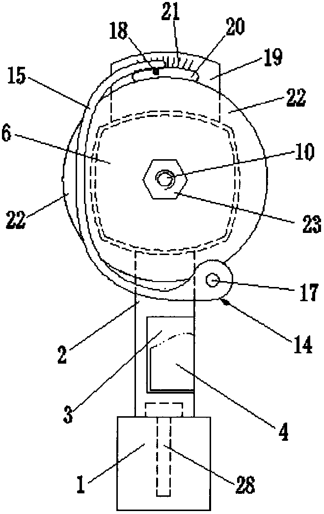
[0017] like figure 1 Shown, depth gauge 19 is fixed on the top of gear box 5. A positioning groove 20 is horizontally opened in the middle of the depth ruler 19 , and a depth line 21 is engraved on the upper edge of the positioning groove 20 .

[0018] like figure 1 , 2 As shown, the milling positioner 14 is a C-shaped object. One end of the cutting and milling positioner 14 is provided with a rotating shaft 17, and the extension of the rotating shaft 17 is fixed on the botto...

example 2

[0022] like figure 1 As shown, a flexible shaft locator installation opening 3 is opened in the middle of the shaft shank 2, and a shaft shank cover 4 matching it is also provided on the flexible shaft locator installation opening 3.

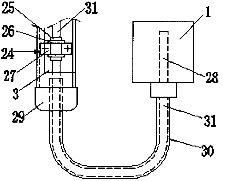
[0023] like image 3 As shown, the flexible shaft positioner 24 is made up of a bearing 27, a slot bolt 25, and a clamping wire 26. The slot bolt 25 passes through the inner hole of the bearing 27, and the clamping wire 26 fixes the slot bolt 25 and the bearing 27 together.

[0024] still as image 3 As shown, one end of the axle shaft 2 is fixedly connected with the bottom of the gear box 5, and the other end is covered with an axle handle head cover 29. The flexible shaft locator 24 is installed in the lumen of the shaft shank 2 from the flexible shaft locator mounting port 3 on the shaft shank 2 . The outer diameter of the bearing 27 on the flexible shaft positioner 24 is consistent with the inner diameter of the axle shaft 2 .

[0025] a...


PUM

PropertyMeasurementUnit
Outer diameteraaaaaaaaaa
Diameteraaaaaaaaaa

Abstract

The invention discloses a hand-held cutting and milling machine which relates to the technical field of cutting and milling tools and is concretely composed of parts such as a power machine, a shaft handle, a drive shaft or a flexible shaft, a gearbox, a cutting and milling piece, a cutting and milling positioner, a depth gauge and the like, wherein one end of the tubular shaft handle is fixed on the lower side edge of the gearbox while the other end is fixed on the power machine; a driven bevel gear is horizontally arranged in the gearbox; a driving bevel gear is longitudinally arranged in the gearbox and meshed with the driven bevel gear; a driving gear shaft is stretched into the tubular cavity of the shaft handle after penetrating through a side shaft sleeve of the gearbox; the drive shaft or the flexible shaft is arranged in the tubular cavity of the tubular shaft handle; one end of the drive shaft or the flexible shaft is connected with the driving gear shaft while the other end is connected with a rotating shaft of the power machine; the cutting and milling piece is arranged on a driven gear shaft; and the cutting and milling positioner is fixedly arranged on the gearbox through the depth gauge and a revolving shaft which is arranged on a regulating ring. The cutting and milling machine is smaller in volume and flexible in operation so that the success rate of replacing a cylinder liner is greatly increased and the work efficiency can be increased by tens times when the dry cylinder liner of a motor is replaced.

Description

technical field [0001] The invention relates to the technical field of cutting and milling tools, in particular to a hand-held cutting and milling machine. Background technique [0002] In auto repair or some hardware repair industries, it is often necessary to use special cutting tools to better accomplish work goals. For example, in the auto repair industry, due to the lack of special tools for replacing engine dry-type cylinder liners, the conventional replacement methods are boring and milling, drawing or rejecting. The boring and milling method needs to dismantle the engine assembly, which requires a large workload and labor Time-consuming; the pulling method requires the cooperation of many people, which is heavy and rough, and is easy to damage the machine body and the working surface; the destructive method is more destructive, and it is not uncommon for the machine body to be damaged by this method. [0003] In the long-term practice of repairing and replacing dry-...

Claims


Application Information

Patent Timeline
IPC IPC(8): B23C1/20
Inventor 庄永雷
Owner 庄永雷
Why Eureka
Try Eureka