Eureka AIR delivers breakthrough ideas for toughest innovation challenges, trusted by R&D personnel around the world.

Polaroid stripping machine and method for stripping polaroid

A polarizer and peeling machine technology, applied in chemical instruments and methods, optics, nonlinear optics, etc., can solve the problems of high static electricity, low efficiency, safety and health hazards of circuits and operators, and achieve the effect of eliminating static electricity accumulation.

Active Publication Date: 2012-08-15
SHENZHEN CHINA STAR OPTOELECTRONICS TECH CO LTD
View PDF5 Cites 15 Cited by
  • Summary
  • Abstract
  • Description
  • Claims
  • Application Information

AI Technical Summary

Problems solved by technology

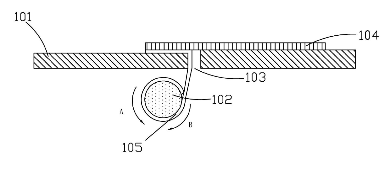
Using the existing polarizer peeling machine, after peeling off the polarizer 105, it is necessary to rotate the roller 102 in the direction A in reverse to remove the polarizer 105 wound on the roller 102, and then perform the next polarizer peeling operation, such an operation The process cannot continuously carry out the polarizer stripping operation, and the efficiency is low
[0004] Moreover, in the process of peeling off the polarizer, the glass substrate 105 slides on the operating platform 101, and the friction force with the operating platform 101 is very large, which will accumulate a lot of static electricity, which is harmful to the safety and health of the circuit on the glass substrate 105 and the operator. are huge hazards

Method used


Image

  • Polaroid stripping machine and method for stripping polaroid
  • Polaroid stripping machine and method for stripping polaroid
  • Polaroid stripping machine and method for stripping polaroid

Examples


Embodiment Construction

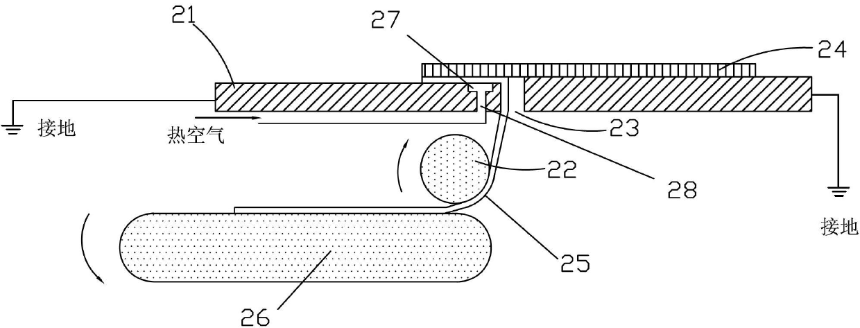
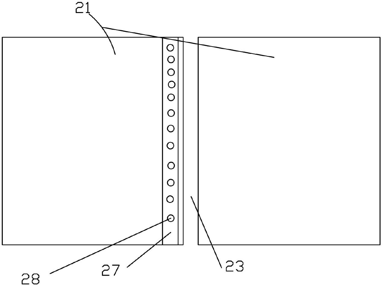
[0030] see figure 2 and image 3 , figure 2 It is a schematic diagram of the longitudinal section structure of a preferred embodiment of the polarizer peeling machine of the present invention, image 3 for figure 2 top view. The polarizer peeling machine of this preferred embodiment comprises an operating platform 21 and a conveyor strip 26 with a translatable surface. The operating platform 21 is provided with a slit 23 as a polarizer stripping position. The strip conveyor belt 26 can The translational surface is located below the slit 23; when the polarizer 25 is peeled off, the glass substrate 24 to be stripped of the polarizer slides along the upper surface of the operating platform 21 and passes through the slit 23, and the peeled off polarizer 25 is spread downwards through the slit 23 and laid on a long strip. The translatable surface of the conveyor belt 26 translates on and with the translatable surface of the elongated conveyor belt 26 . As an option, the elo...


PUM


Abstract

The invention relates to a polaroid stripping machine and a method for stripping a polaroid. The polaroid stripping machine comprises an operation platform and a conveying device with a translatable surface, wherein the operation platform is provided with a gap which is used as a polaroid stripping position; the translatable surface of the conveying device is located below the gap; when the polaroid is stripped, a glass substrate with the polaroid to be stripped slides through the gap along the upper surface of the operation platform; and the stripped polaroid downwards extends and is paved on the translatable surface of the conveying device by the gap, and horizontally moves along with the translatable surface of the conveying device. The polaroid stripping machine and the method for stripping the polaroid, disclosed by invention, change the polaroid stripping operation into a continuous process, can eliminate the damages of static electricity accumulation in the polaroid stripping process to a panel and an operator, can heat the polaroid, and reduce the stripping strength and the fragmenting possibility.

Description

technical field [0001] The invention relates to a polarizer stripping technology, in particular to a polarizer stripping machine and a method for stripping a polarizer. Background technique [0002] In the TFT-LCD (Thin Film Field Effect Transistor Liquid Crystal Display) manufacturing process, the attachment effect of the polarizer has an important impact on the display effect of the LCD. For situations such as insufficient attachment accuracy, bubbles, and scratches on the polarizer, it is necessary to replace the attached The attached polarizer is peeled off from the glass substrate and then reattached to meet the quality requirements of the LCD. [0003] The existing method for peeling off the polarizer is as follows: firstly use a blade to cut into the bonding seam between the polarizer and the glass substrate to lift the front end of the polarizer; then pull the raised front end of the polarizer until the polarizer is separated from the glass substrate. see figure 1 ...

Claims


Application Information

Patent Timeline
Patent Type & Authority Applications(China)
IPC IPC(8): B32B38/10G02F1/1335
CPCG02F1/1335G02F1/133528B32B38/10G02F1/1303B32B43/006
Inventor 钟新辉
Owner SHENZHEN CHINA STAR OPTOELECTRONICS TECH CO LTD
Why Eureka
Eureka Blog
Learn More