Self-tangency broaching anchor bolt

An anchor bolt and self-cutting technology, applied in the direction of light impact tools, connecting components, pins, etc., can solve the problems of reduced milling continuity, low milling continuity, and unsatisfactory milling performance of metal materials, etc., to achieve the goal of improving milling performance Effect

Inactive Publication Date: 2012-08-15
王春华
View PDF8 Cites 7 Cited by
  • Summary
  • Abstract
  • Description
  • Claims
  • Application Information

AI Technical Summary

Problems solved by technology

[0005] However, the milling function of the above two milling structures of self-cutting and reaming anchor bolts is still not good enough. It is a vertical relationship, which causes the anchor bolt structure itself to have a small cutting force on the material, which is an effect with the passivation or chipping of the milling cutter. It is difficult to apply effective milling force to the steel bar during the milling process; the second reason is that the anchor bolt expands In the later period, because the distance between cracks 1-4 becomes larger, the milling continuity of each cutter tooth decreases. As the expansion progresses, the milling force becomes smaller and the milling process becomes slower and slower. In fa

Method used


Image

  • Self-tangency broaching anchor bolt
  • Self-tangency broaching anchor bolt
  • Self-tangency broaching anchor bolt

Examples


Embodiment 1

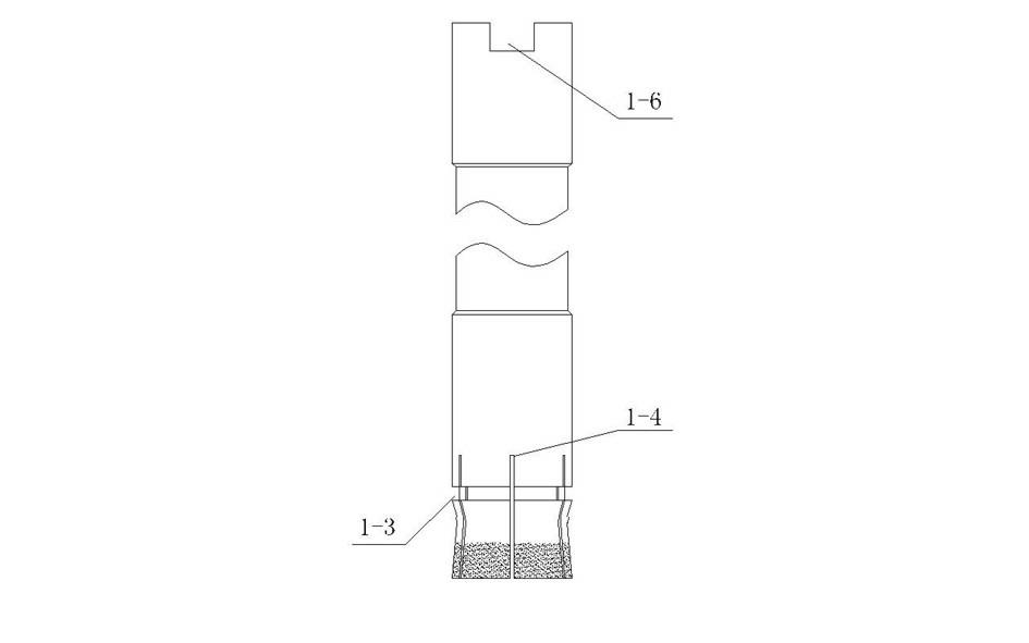
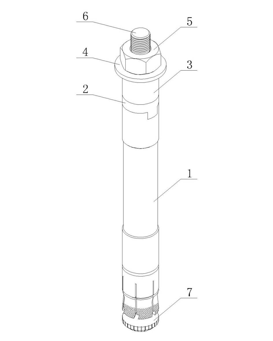
[0051] Such as image 3 , Figure 4 , Figure 5 Shown is one of the designed embodiments of the present invention. In this embodiment, the self-cutting and reaming anchor bolt includes a sleeve 1 with an expansion structure at the lower end, and a slot 1 fitted with an installation tool at the upper end of the sleeve 1. -6, the expansion structure is composed of slits 1-4 to divide the wall of the lower end of the sleeve 1, including several expansion pieces, in this embodiment, 6 expansion pieces are used, and the common 4 pieces, and other appropriate numbers can also be used expansion film. The lower end of the expansion structure is provided with a milling structure, which includes cutter teeth 1-1 uniformly distributed around the axis of the sleeve 1. The structure of the cutter teeth 1-1 can be referred to Figure 5 .

[0052] The side of the cutter tooth 1-1 that rotates toward the sleeve 1 has a milling blade 1-2, the blade 1-2 is located at the lower end of the cr...

Embodiment 2

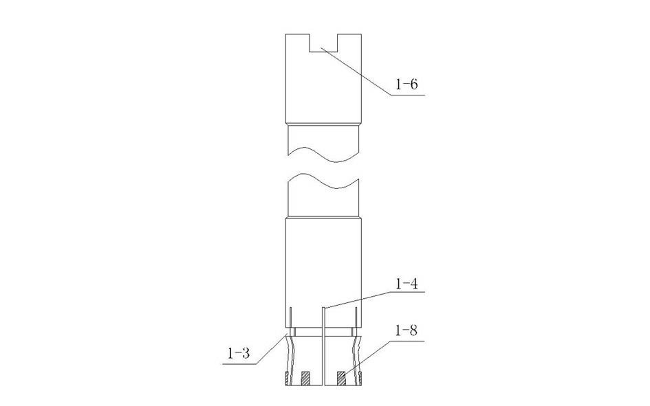
[0060] Figure 6 Shown is the 2nd kind of embodiment of the present invention, compared with embodiment 1, cutter tooth 1-1 is welded with cemented carbide block at blade 1-2 position, and cemented carbide has hardness high, wear-resisting, strength and toughness Excellent performance, heat resistance, corrosion resistance and a series of excellent properties, it is a common constituent material in milling tools. If the size of the part allows, the cemented carbide block can be fixed by riveting.

Embodiment 3

[0062] Figure 7 Shown is the third embodiment of the present invention. Compared with Example 1, the lower end of the expansion sheet is provided with two cutter teeth 1-1. The cutter teeth 1-1 have the same structure but the width is reduced. The cutter teeth 1-1 The increased density can speed up the milling frequency of the milling mechanism and increase the milling speed.

[0063] Correspondingly, a hard material milling layer is provided on the working surface of the cutter tooth 1-1. The hard material milling layer is composed of diamond or boron nitride, and a hard alloy coating can also be used. The milling layer is brazed or electroplated. Set on the working face of the cutter tooth.


PUM


Abstract

The invention discloses a self-tangency broaching anchor bolt comprising a sleeve, wherein the lower end of the sleeve is provided with an expansion structure, the upper end of the sleeve is provided with a clamp groove which is embedded with an installing tool, the expansion structure comprises a plurality of expansion pieces, the lower end of the expansion structure is provided with a milling structure, the milling structure comprises a plurality of cutter teeth which are peripherally and evenly distributed around the axis of the sleeve, one sides, which face to a sleeve rotating direction, of the cutter teeth are provided with cutting edges, the cutting edges are slantwise arranged opposite to the end face of the sleeve, and the bottom ends of the cutting edges are convex towards the sleeve rotating direction; and the cutter teeth are directly machined by the lower end of the expansion structure, a hard material wear layer is arranged on the working faces of the cutter teeth or the cutting edges are provided with hard alloy blocks, or the cutter teeth are wholly formed by the hard alloy and are fixed at the lower end of the expansion structure. The self-tangency broaching anchor bolt uses the milling principle of a milling cutter, so that the cutting edges are matched with the hard alloy or hard material wear layer, therefore, the transverse and lengthways milling performance can be greatly improved when the anchor bolt is expanded.

Description

technical field [0001] The invention relates to a self-cutting reaming anchor bolt, in particular to an expansion anchor bolt which automatically reams holes during the expansion process and can not only mill concrete but also metal materials in the concrete. Background technique [0002] When the existing post-reaming anchor bolt application technology is installed, the drill bit is used to drill holes on the concrete substrate, and then the bottom end is reamed with a special reaming drill bit. After the head of the anchor bolt expands, it forms a lock with the reaming space. Solid structure, no expansion stress. However, in actual reaming, steel bars are often encountered in concrete. The current design of reaming drills is only for cutting and reaming concrete substrates. The cutting performance of steel bars is very poor, and it is impossible to ream concrete with steel bars. At the same time, the reaming drill bit has defects such as cumbersome operation, inaccurate p...

Claims


Application Information

Patent Timeline
IPC IPC(8): F16B13/06B25D17/00
Inventor 王春华
Owner 王春华
Why Eureka
Try Eureka