
Radiating fin and base combination structure

A technology of heat dissipation fins and combined structure, which is applied to heat exchange equipment, lighting and heating equipment, etc., can solve the problems of unable to play a stable combination, poor clamping effect, uneven heat dissipation fins, etc.

Active Publication Date: 2013-12-18
DONG GUAN HAN XU HARDWARE & PLASTIC TECH CO LTD
View PDF1 Cites 0 Cited by
  • Summary
  • Abstract
  • Description
  • Claims
  • Application Information

AI Technical Summary

Problems solved by technology

[0003] The above-mentioned prior patent technology mainly pre-forms a drop-shaped, conical or circular larger protrusion at the bottom of the heat dissipation fin, and the opening of the base groove is large at the top and small at the bottom, so the heat dissipation fin can only be opened from The side of the base groove is inserted, and then punched and clamped to complete the combination. Since this design cannot be directly inserted into the base groove in a vertical direction, it will be quite complicated and inconvenient to assemble.
[0004] Or as in the U.S. Patent No. 6758262, although the heat dissipation fins are directly inserted into the groove of the base in a vertical direction, the clamping purpose can only be achieved by using the extrusion deformation on both sides of the groove of the base, and the clamping force is concentrated At the deformation position on both sides of the opening of the groove, there are only two point-shaped clamping forces. Therefore, the clamping effect is not good, and the role of stable combination cannot be exerted, and the uneven heights of the heat dissipation fins are prone to occur. phenomenon, and may shake or even fall off
In addition, there are also people who form a reflexed part or an L-shaped bent part at the bottom of the heat dissipation fins in advance, and then insert them into the groove of the base for stamping and bonding. Possible sideways deflection

Method used


Image

  • Radiating fin and base combination structure
  • Radiating fin and base combination structure
  • Radiating fin and base combination structure

Examples


Embodiment Construction

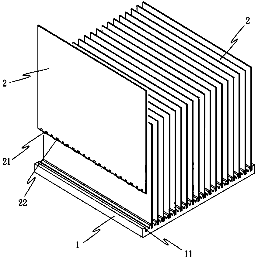
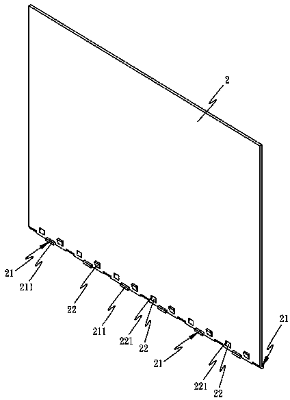
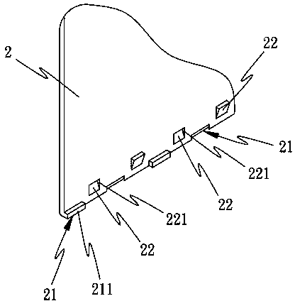
[0030] The present invention will be further described below in conjunction with the accompanying drawings and specific embodiments.

[0031] Such as figure 1 As shown, the present invention is a combination structure design of a heat dissipation fin and a base, which at least includes a base 1 and a plurality of heat dissipation fins 2, and the base 1 is provided for corresponding insertion of a plurality of heat dissipation fins 2 The grooves 11, the heat dissipation fins 2 are stamped at the bottom to form a plurality of bending parts 21 in staggered directions (such as Figure 2 to Figure 4 shown), and using the staggered bending part 21, it can be inserted into the groove 11 to form a stable stand (such as Figure 5 ), and then through casting or extrusion, the bottom ends of the heat dissipation fins 2 are buried and combined (such as Image 6 ) or tight clamping (as Figure 7 ) in the groove 11 to achieve a stable positioning combination to ensure that the combinatio...


PUM


Abstract

The invention relates to a radiating fin and base combination structure design. The radiating fin and base combination structure comprises a base and a plurality of radiating fins, a plurality of adjacent grooves are arranged on the radiating base for respectively implanting the radiating fins in an inserting way, the radiating fins are tied at the bottom end to be stamped and form bending parts and wing hook parts which are intersected, so that the bottom ends of the radiating fins are inserted in the grooves of the radiating base in a matching manner and can be combined by burying or tightly clamped in the grooves by means of a pouring or extrusion manner, the radiating fins can be buried or clamped in the grooves of the radiating base by utilizing the bending parts and the wing hook parts which are intersected at the bottom end, so as to achieve the stable positioning and combining effects.

Description

technical field [0001] The present invention provides a combination structure design of heat dissipation fins and base, which is preset at the bottom of each heat dissipation fin to form interlaced bent parts and wing hooks, so as to make the heat dissipation fins The sheet can be quickly and firmly combined with the base groove. Background technique [0002] Conventional heat sinks mainly consist of a base and a plurality of heat dissipation fins, or more than one heat pipe can be embedded in the base. For the combination of the base and heat dissipation fins, in addition to the traditional welding technology, there are also methods such as U.S. Patent No. 5014776 is to pre-insert the cooling fins in the groove of the base, and then clamp and combine the cooling fins to the groove of the base by stamping to achieve the purpose of combining the cooling fins and the base. [0003] The above-mentioned prior patent technology mainly pre-forms a drop-shaped, conical or circular...

Claims


Application Information

Patent Timeline
Patent Type & Authority Patents(China)
IPC IPC(8): F28F7/00
Inventor 黄崇贤
Owner DONG GUAN HAN XU HARDWARE & PLASTIC TECH CO LTD
Learn More