Eureka AIR delivers breakthrough ideas for toughest innovation challenges, trusted by R&D personnel around the world.

High-efficiency beam combination laser fiber and drawing method thereof

A fiber drawing and beam-shaping technology, which is applied to lasers, clad optical fibers, optical waveguides, etc., can solve problems such as inability to realize multi-point pump light injection, inability to strip according to requirements, and difficulty in effective control and adjustment. Excellent pump light coupling performance, good optical performance and reliability, and easy combination

Active Publication Date: 2013-12-25
FENGHUO COMM SCI & TECH CO LTD
View PDF2 Cites 4 Cited by
  • Summary
  • Abstract
  • Description
  • Claims
  • Application Information

AI Technical Summary

Problems solved by technology

Although the single optical fiber drawing technology is very mature at present, there are still many difficulties in the simultaneous drawing of multiple optical fibers, such as the drawing tension, temperature, and corresponding optical fiber of each preform during the combined drawing process of multiple optical fiber preforms. There are differences in the coating pressures, and it is difficult to effectively control and adjust
Moreover, the current combined drawing method of preforms uses a plurality of cylindrical preforms to combine and then draws, and in order to ensure that the optical fibers can be effectively fused, the conditions of low speed and high tension are adopted, and the optical fiber preforms will be melted and combined with each other, so the drawn The quartz parts of the fiber are fused and tightly bonded to each other, and cannot be peeled off as required, so it is also impossible to achieve multi-point pump light injection in the length direction.

Method used


Image

  • High-efficiency beam combination laser fiber and drawing method thereof
  • High-efficiency beam combination laser fiber and drawing method thereof
  • High-efficiency beam combination laser fiber and drawing method thereof

Examples


Embodiment 1

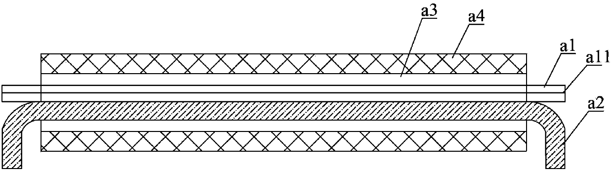
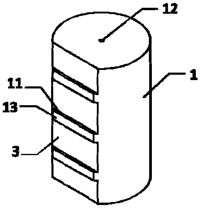
[0043] Such as Figures 3 to 7 As shown, the rare earth-doped gain fiber preform 1 in the core area is processed inwardly from the base plane 13 to form 25 ribs 11, and the height of the ribs 11 (that is, the distance from the processing plane 3 to the base plane 13) is 1.5mm , the length of the ribs 11 along the fiber axis is 10 mm, and the distance between the centers of two adjacent ribs 11 is 12 mm. The pump optical fiber preform 2 of the quartz component is processed inwardly from the base plane 13, and at the position corresponding to the rib 11 of the gain optical fiber preform 1, a plurality of rectangular grooves 21 are formed, and the processing of the grooves 21 The depth is 1.5mm.

[0044] Combine the processed gain fiber preform 1 with a rare earth doped core diameter of 1.7 mm and a cladding of 17.3 mm with the pump fiber preform 2 with a grooved cladding of 17.3 mm, that is, the convexity of the gain fiber preform 1 The rib 11 is embedded in the groove 21 of t...

Embodiment 2

[0049] Such as Figures 3 to 7 As shown, the rare earth-doped gain fiber preform 1 in the core area is processed inwardly from the base plane 13 to form four ribs 11, and the height of the ribs 11 (that is, the distance from the processing surface 3 to the base plane 13) is 4 mm. The ribs 11 have a length of 50 mm along the fiber axis, and the distance between the centers of two adjacent ribs 11 is 120 mm. The pump optical fiber preform 2 of the quartz component is processed inwardly from the base plane 13, and at the position corresponding to the rib 11 of the gain optical fiber preform 1, a plurality of rectangular grooves 21 are formed, and the processing of the grooves 21 The depth is 4mm.

[0050] Combine the processed gain fiber preform 1 with a rare earth doped core diameter of 3.6 mm and a cladding of 36 mm with the pump fiber preform 2 with a cladding of 36 mm after slotting, that is, the rib 11 of the gain fiber preform 1 Embedded in the groove 21 of the pump optic...


PUM

PropertyMeasurementUnit
lengthaaaaaaaaaa
widthaaaaaaaaaa
lengthaaaaaaaaaa

Abstract

The invention discloses a drawing method of a high-efficiency beam combination laser fiber, and relates to the technical field of fiber laser transmission and amplification. The method comprises the steps that S1, a basic plane is arranged on each of the side surfaces of a gain fiber preform and a pump fiber preform; the basic plane of the gain fiber preform is processed inwards; a plurality of ribs are raised; planes on the two sides of each rib are processing surfaces; a plurality of grooves are formed inwards in the basic plane of the pump fiber preform; the ribs are matched with the grooves; S2, the ribs of the gain fiber preform are embedded into the grooves of the pump fiber preform; after combination of the ribs and the grooves, one end of a whole combination body is fixed by a taper to form a beam combination laser fiber preform; and S3, the beam combination laser fiber preform is drawn into the beam combination laser fiber by wire drawing. The drawing method is higher in technology repeatability; and obtained beam combination laser can achieve pump fiber stripping in a set area, and facilitates achieving multipoint pump photoinjection in a length direction of the beam combination laser fiber.

Description

technical field [0001] The invention relates to the technical field of optical fiber laser transmission and amplification, in particular to a high-efficiency parallel beam laser optical fiber drawing method and an optical fiber. Background technique [0002] Fiber lasers essentially convert low-quality pump lasers into higher-quality laser outputs. Due to the continuous expansion of application fields, the demand for output power of fiber lasers is also increasing. Now high-power fiber lasers and fiber amplifiers are mainly used. It is a double-clad doped fiber, and compared with the divergence angle of the multimode pump beam emitted by the semiconductor pump laser, the inner cladding diameter of the double-clad doped fiber is very small, so how to efficiently couple the pump light to the double-clad fiber The inner cladding of cladding fiber is the core technology for obtaining high-power fiber laser output. [0003] At present, pump coupling technology can be roughly div...

Claims


Application Information

Patent Timeline
Patent Type & Authority Applications(China)
IPC IPC(8): C03B37/028G02B6/02
CPCH01S3/094019C03B37/01205C03B37/01228C03B37/0253C03B37/027C03B2201/34C03B2203/02C03B2203/10C03B2203/32C03B2203/40C03B2205/40H01S3/06729H01S3/06737H01S3/094053
Inventor 杜城陈伟李诗愈柯一礼莫琦张涛罗文勇杜琨但融
Owner FENGHUO COMM SCI & TECH CO LTD
Why Eureka
Eureka Blog
Learn More