
Connector production method and connector structure

A production method and connector technology, which is applied in the parts, connections, and assembly/disassembly of contact pieces of connection devices, can solve problems such as difficult demoulding, uneven connection methods, and irregular terminal arrangements, etc., to achieve Simplified workflow, compact and firm assembly, simple and compact structure

Active Publication Date: 2016-08-03
韶关胜蓝电子科技有限公司
View PDF6 Cites 4 Cited by
  • Summary
  • Abstract
  • Description
  • Claims
  • Application Information

AI Technical Summary

Problems solved by technology

However, the structure of each part of the connector in the prior art is relatively complicated, and it is necessary to use a variety of molds to produce each part separately during processing and production, and then assemble the parts together
Moreover, the ways of connecting with each other are also uneven. Due to the relatively fine and large number of components during assembly, such a structure and installation method are prone to problems of matching errors and unstable matching.
The traditional rear rubber core module is provided with an inlay groove for the insertion of the terminal. First, the terminals are arranged neatly, and then the entire row of terminals is inserted into the groove. demoulding, and it is easy to make the terminal installation unstable, which will lead to irregular arrangement of the terminals after installation
Once the assembly is wrong or unqualified, these parts will be discarded or reprocessed for reuse, so the increase of unqualified products not only wastes processing costs, but also extends a series of follow-up processing costs

Method used


Image

  • Connector production method and connector structure
  • Connector production method and connector structure
  • Connector production method and connector structure

Examples


Embodiment Construction

[0033] The present invention will be described in detail below in conjunction with specific embodiments and accompanying drawings.

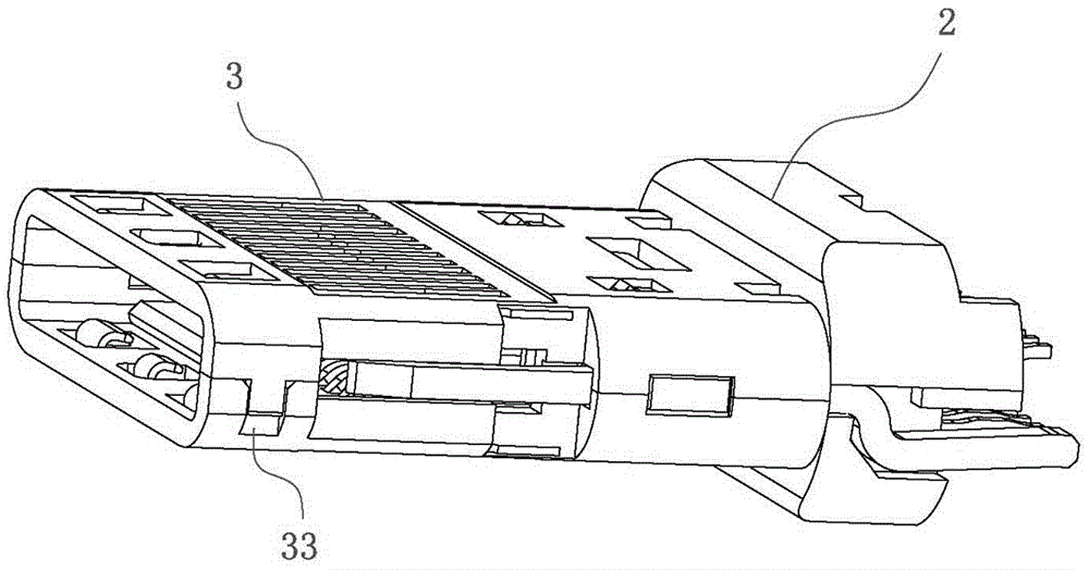
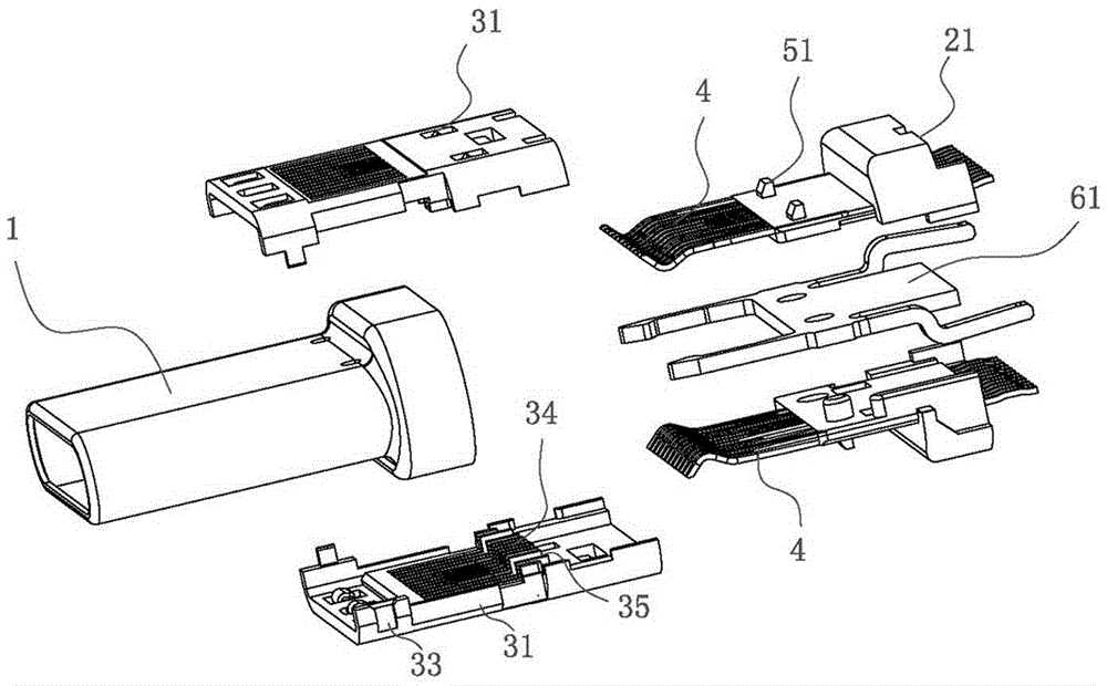
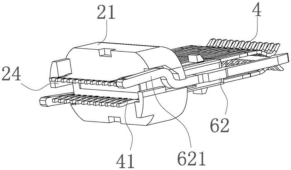
[0034] A production method of a connector provided by the present invention has a structure such as Figure 1 to Figure 6 shown, including the following steps:

[0035] Step A: Injection molding the front rubber core unit 31 and the rear rubber core unit 21 respectively, wherein several terminals 4 are arranged in a row and placed in the injection mold, and the rear rubber core unit 21 is injection molded on the neatly arranged terminals 4 ;

[0036] Step B: fixedly connect the front rubber core unit 31 to the rear rubber core unit 21, and one front rubber core unit 31 and one rear rubber core unit 21 form a connector unit;

[0037] Step C: Any two connector units are buckled together to form a connector body, wherein the front rubber core unit 31 is buckled to form the front rubber core module 3, and the rear rubber core unit 21 is buckled to ...


PUM


Abstract

The present invention provides a connector production method. When production, a row of terminals are subjected to injection moulding to form a rear rubber core unit, the rear rubber core unit is fixedly connected with a front rubber core unit to form a connector unit, and any two connector units are assembled together to form the main body of the whole connector. The terminals and the rear rubber core unit are steadily fixed, so that the problem is solved that a traditional injection moulding rear rubber core module group is difficult to demould, it is ensured that the terminals are tidily arranged at the rear rubber core unit, and the requirement is satisfied that the connector is compactly and firmly assembled. The present invention further provides a connector structure, and the connector structure is cooperated with the production method provided by the invention. The rear rubber core module group is formed by two rear rubber core units with the same structure through buckling, and the front rubber core module group is formed by two front rubber core units with the same structure through buckling, and the rear rubber core units and the front rubber core units are produced on a large scale, then any two rear rubber core units and any two front rubber core units can be combined.

Description

technical field [0001] The invention relates to the technical field of connectors, in particular to a production method and structure of a connector. Background technique [0002] With the popularization of a large number of servers and personal computers that support USB, it is the general trend that USB gradually becomes the standard interface of PCs. The Chinese meaning of USB (UniversalSerialBus) is "Universal Serial Bus", which is a new interface technology applied in the field of PC. As a PC interconnection protocol widely used, USB makes the connection of peripherals to computers more efficient and convenient. Peripherals such as keyboards, mice, modems, printers, etc. are generally connected to the computer through USB connectors. The USB connector has the characteristics of fast transmission speed, support for hot plugging and connection of multiple devices, and has been widely used in various external devices. Existing connectors generally include a front rubber...

Claims


Application Information

Patent Timeline
Patent Type & Authority Applications(China)
IPC IPC(8): H01R43/18H01R43/20H01R13/405
CPCH01R13/405H01R43/18H01R43/20
Inventor 陈怀权
Owner 韶关胜蓝电子科技有限公司
Learn More