Gas-liquid measurement method with super-small flow

A measurement method and small flow technology, applied in the direction of volume measurement, measurement capacity, liquid/fluid solid measurement, etc., can solve the problems affecting measurement work, measurement difficulty, blockage, etc. The effect of turndown ratio

Inactive Publication Date: 2012-08-15
宁波威瑞泰默赛多相流仪器设备有限公司
View PDF6 Cites 4 Cited by
  • Summary
  • Abstract
  • Description
  • Claims
  • Application Information

AI Technical Summary

Problems solved by technology

In addition, the liquid phase produced by these gas fields contains a large amount of dirt. If a small-caliber flowmeter is used to measure, problems such as clogging and jamming will occur, and some small liquid plugs will also occur at the wellhead, which will affect normal operation. Metrology work
Therefore, it will be very difficult to measure ultra-low liquid production with traditional flowmeters and metering methods

Method used


Image

  • Gas-liquid measurement method with super-small flow
  • Gas-liquid measurement method with super-small flow
  • Gas-liquid measurement method with super-small flow

Examples


Embodiment 1

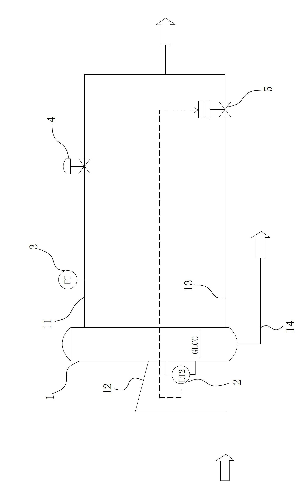
[0033] Such as figure 1 Shown is the gas-liquid metering system used in the ultra-small flow gas-liquid metering method of the present invention, which includes a gas-liquid separator 1, wherein the upper, middle, and lower side walls of the gas-liquid separator 1 are respectively provided with The gas-liquid separator 1 internally communicated with the gas outlet pipe 11, the raw liquid input pipe 12, and the liquid outlet pipe 13. The gas-liquid separator 1 is also provided with a liquid level transmitter 2 whose gas-liquid flow direction is as follows figure 1 As shown by the arrow in;

[0034] The steps of the ultra-small flow gas-liquid metering method of the present invention are as follows:

[0035] (1) The mixture to be metered enters the metering system from the raw liquid input pipe 12, and the mixture to be metered is separated into gas and liquid through the gas-liquid separator 1;

[0036] (2) The separated gas phase is measured by the gas phase flow meter 3 connected ...

Embodiment 2

[0049] The difference between the second embodiment and the first embodiment lies in the steps of liquid phase metering. The specific steps are as follows:

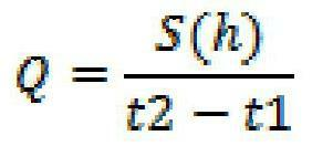
[0050] (i) Set a specific height and determine the time when the liquid injection in the gas-liquid separator 1 reaches the set height. Specifically, the liquid injection height inside the gas-liquid separator 1 is controlled by the liquid level switch valve 5. The liquid level switch Valve 5 is an on-off valve that opens and closes intermittently. When it is closed, record the time t1 at this time. When the liquid injection in the gas-liquid separator 1 reaches the set height, record the time t2 at this time, and the measurement ends. , The flow calculation formula is:

[0051] Q = s ( h ) t 2 - t 1

[0052] Q: Volume flow;

[0053] S: the cross-sectional area of ​​the inner surface of the separator;

[0054] h: The specific height set.

[0055] (ii) The liquid phase switch valve 5 is opened to d...


PUM


Abstract

The invention relates to a gas-liquid measurement method with super-small flow, which comprises the following steps that (1) after mixture to be measured enters into a measuring system from a primary liquid input pipe, the gas and the liquid of the mixture to be measured are separated through a gas-liquid separator; (2) the gas phase of a gas-phase substance which is separated is measured through a gas phase flowmeter which is connected onto a gas outlet pipe; and (3) a liquid-phase substance which is separated enters a liquid-phase switch valve which is arranged on a liquid outlet pipe through the liquid outlet pipe, and the liquid phase is measured under the joint action of the liquid phase switch valve, a liquid level transmitter and the gas-liquid separator. Compared with the prior art, the gas-liquid measurement method with super-small flow has the advantages that the gas-liquid measurement can be realized when the amount of liquid is extremely small; the method can ensure that the operation is reliable and has a wider range ratio; and the most important is that the measurement method can reflect the production change of a single well in real time.

Description

Technical field [0001] The invention relates to a gas-liquid metering method used in single well metering in a gas field, in particular to a gas-liquid metering method with an ultra-small flow. Background technique [0002] In natural gas fields, some gas wells have very little liquid content, and many single wells have gas-liquid ratios below 10000m3 / 0.1m3. In addition, the liquid phase produced by these gas fields contains a large amount of dirt. If a small-caliber flow meter is used to measure, it will cause blockages, jams, etc., and some small liquid plugs will be generated at the wellhead, which affects normal Measuring work. Therefore, it is very difficult to measure ultra-low liquid production using traditional flow meters and metering methods. [0003] On the other hand, the existing devices for gas-liquid separation and metering, such as the Chinese patent "A cyclonic gas-liquid separator" with the patent number ZL200720108504.0 (publication number CN201055811Y) A devi...

Claims


Application Information

Patent Timeline
Patent Type & Authority Applications(China)
IPC IPC(8): G01F1/42G01F15/08
Inventor 仇晨钟春祥郑金果方再新
Owner 宁波威瑞泰默赛多相流仪器设备有限公司
Why Eureka
Try Eureka