
Online monitoring system of high-voltage equipment

A high-voltage equipment and monitoring system technology, applied in the field of monitoring systems, can solve the problems of deploying many professional testing personnel, unable to supply power, consuming a lot of manpower and material resources, saving manpower and material resources, ensuring safe and stable work, and being flexible and expandable. Effect

Inactive Publication Date: 2012-08-15
SHANGHAI MUNICIPAL ELECTRIC POWER CO +1
View PDF6 Cites 19 Cited by
  • Summary
  • Abstract
  • Description
  • Claims
  • Application Information

AI Technical Summary

Problems solved by technology

[0002] At present, there are substations widely distributed in the power grid system, and various high-voltage electrical equipment are installed in the substations. To maintain the stable operation of the power grid system, it is necessary to monitor each high-voltage equipment in real time. In the prior art, the monitoring of high-voltage equipment The technology includes manual monitoring and testing after the high-voltage equipment is disconnected. The disadvantage is that if the manual real-time monitoring equipment is used, many professional testing personnel are required to work, which consumes a lot of manpower and material resources; at the same time, if the high-voltage equipment is disconnected. For testing, the power grid needs to be cut off before testing the high-voltage equipment, which will cause the road to fail to supply power and make the power grid unstable

Method used


Image

  • Online monitoring system of high-voltage equipment
  • Online monitoring system of high-voltage equipment
  • Online monitoring system of high-voltage equipment

Examples


Embodiment Construction

[0015] Specific embodiments of the present invention will be further described below in conjunction with the accompanying drawings.

[0016] The invention discloses an online monitoring system for high-voltage equipment, which is used for real-time monitoring of high-voltage equipment in substations distributed in various regions in a grid system.

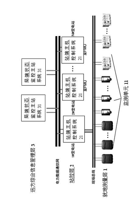
[0017] Such as figure 1 As shown, the high-voltage equipment on-line monitoring system adopts a three-layer system structure, which is designed according to a layered distributed system. The building block structure has flexible scalability. The system includes an on-site measurement layer 1, a station control layer 2 connected to the on-site measurement layer 1 through the RS485 industrial field bus network, and a remote integrated information management layer 3 connected to the station control layer 2 through a power data communication network network.

[0018] The on-site measurement layer 1 includes a number of monitoring unit...


PUM


Abstract

The invention discloses an online monitoring system of high-voltage equipment. The system adopts a three-layer system structure and comprises an in-place measuring layer, a station control layer and a distant-place comprehensive information management layer, wherein the station control layer is connected with the in-place measuring layer through a field bus; the distant-place comprehensive information management layer is connected with the station control layer through a network; the in-place measuring layer comprises a plurality of monitoring units which are arranged in each high-voltage equipment; the station control layer comprises a plurality of station end main engine control systems which are respectively connected with the monitoring units through the bus; and the distant-place comprehensive information management layer comprises a partial end state monitoring main station system which is connected with a plurality of the station end main engine control systems through the network. The online monitoring system is designed into the three-layer system structure and has flexible expandability; the online monitoring system realizes that the high-voltage equipment in each transformer substation is uniformly managed by the distant-place comprehensive information management layer and realizes that the systematical and networked real-time monitoring on the high-voltage equipment in a large range of the transformer substation; and the online monitoring system guarantees that a power grid system safely and stably works and saves a large quantity of manpower and material resources.

Description

technical field [0001] The invention relates to a monitoring system for a power grid system, in particular to an online monitoring system for high-voltage equipment. Background technique [0002] At present, there are substations widely distributed in the power grid system, and various high-voltage electrical equipment are installed in the substations. To maintain the stable operation of the power grid system, it is necessary to monitor each high-voltage equipment in real time. In the prior art, the monitoring of high-voltage equipment The technology includes manual monitoring and testing after the high-voltage equipment is disconnected. The disadvantage is that if the manual real-time monitoring equipment is used, many professional testing personnel are required to work, which consumes a lot of manpower and material resources; at the same time, if the high-voltage equipment is disconnected. For detection, it is necessary to cut off the power grid before testing the high-vol...

Claims


Application Information

Patent Timeline
IPC IPC(8): G01R31/00
Inventor 陆骏
Owner SHANGHAI MUNICIPAL ELECTRIC POWER CO
Learn More