LED lamp capable of being coded

An LED lamp and coding technology, which is applied in the layout of electric lamp circuits, cooling/heating devices of lighting devices, lighting and heating equipment, etc., can solve the problems of high hardware cost of matching address modification, inability of users to change by themselves, and radio frequency interference remote control, etc. Achieve high power, high efficiency, high luminous flux, stepless dimming, solve system stability problems, and good heat dissipation

Inactive Publication Date: 2014-01-15
江苏中缘植物光照股份有限公司
View PDF8 Cites 3 Cited by
  • Summary
  • Abstract
  • Description
  • Claims
  • Application Information

AI Technical Summary

Problems solved by technology

[0004] The purpose of the present invention is to provide a coded LED lamp to solve the problem of radio frequency remote control lamps in the prior art. The addresses of the radio frequency remote control lamps are uniformly set by the factory, and the user cannot change them by themselves, and the high-end products on the market also need to be set by special software and modified accordingly. The address hardware costs are high and the operation is complicated and difficult to understand. If the radio frequency wireless product cannot allow users to adjust and modify the controlled address according to different application occasions, there will be problems of radio frequency interference or remote control failure.

Method used


Image

  • LED lamp capable of being coded
  • LED lamp capable of being coded
  • LED lamp capable of being coded

Examples


Embodiment Construction

[0024] Preferred embodiments of the present invention will be described in detail below in conjunction with the accompanying drawings.

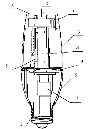
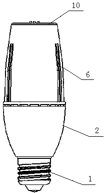
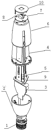
[0025] like figure 1 , figure 2 and image 3 As shown, this embodiment provides a coded LED lamp, including a threaded lamp cap 1, a lamp holder 2, a profile radiator 4, an aluminum substrate wiring board 9, a drive power supply module 3, a light source module, and an MCU main control module 7 , the translucent cover 6, the upper cover 10 and the remote controller 11 for transmitting control signals, the threaded lamp holder 1, the lamp holder 2, the translucent cover 6 and the upper cover 10 are arranged in sequence, and the translucent cover 6 is covered in On the profile radiator 4, the light source module is arranged on the profile radiator 4, the top of the profile radiator 4 is provided with an MCU main control module 7, and the bottom of the profile radiator 4 is provided with an aluminum The substrate wiring board 9, the lamp hold...


PUM


Abstract

The invention provides an LED lamp capable of being coded. The LED lamp capable of being coded comprises a threaded lamp cap, a lamp holder, a section bar heat radiator, an aluminum substrate wiring board, a driving power supply module, a light source module, an MCU main control module, a light transmitting cover, an upper cover and a remote controller used for transmitting a control signal. The LED lamp capable of being coded can achieve full color lighting with high power, high efficiency and high luminous flux and achieve stepless dimming of full color. The LED lamp capable of being coded has the advantages of being simple in structure, good in heat dissipation and convenient to assemble and disassemble. A coder special for address change is installed so that addresses on bulbs can be conveniently and easily changed according to different applications through the coder, and therefore the LED lamp can be applied to different occasions of one-to-one monitoring such as single table lamp monitoring or one-to-many monitoring such as one-to-ten crystal chandelier monitoring. The MCU main control module and the coder are arranged on the LED lamp in an integrated mode, so that the control sequence can be set freely by a user and integration and systematization are achieved.

Description

technical field [0001] The invention relates to a coded LED lamp. Background technique [0002] At present, there are two types of wireless remote control lighting products on the market: 1. Infrared remote control: directional and non-penetrating, generally used in one-to-one remote control in barrier-free spaces; 2. Radio frequency wireless remote control, non-directional and penetrating , through the setting of the radio frequency wireless address, one-to-one remote control or one-to-many remote control can be carried out. However, most of the radio frequency remote control lamps on the market are uniformly set by the factory, and users cannot change them by themselves. However, high-end products on the market also need to be set through special software, and the hardware cost of modifying the address is high and the operation is complicated and difficult to understand. Interference or remote control failure. [0003] The above-mentioned problems should be c...

Claims


Application Information

Patent Timeline
Patent Type & Authority Applications(China)
IPC IPC(8): F21V17/00F21V23/00F21V29/00H05B37/02F21Y101/02F21V29/503F21V29/71F21Y113/20F21Y115/10
Inventor 史杰
Owner 江苏中缘植物光照股份有限公司
Why Eureka
Try Eureka