Eureka AIR delivers breakthrough ideas for toughest innovation challenges, trusted by R&D personnel around the world.

Manufacturing method for an optical connector

A manufacturing method and technology of optical connectors, applied in the coupling of optical waveguides, light guides, optics, etc., can solve problems such as cost increase

Inactive Publication Date: 2012-08-15
NITTO DENKO CORP
View PDF9 Cites 8 Cited by
  • Summary
  • Abstract
  • Description
  • Claims
  • Application Information

AI Technical Summary

Problems solved by technology

[0010] However, as described above, the conventional manufacturing method of an optical connector that uses a fixing agent such as an adhesive in the fixing process of the optical waveguide has the following problems, that is, in addition to the material cost of the fixing agent and the need for fixing work In addition to the workload (man-hours), the grinding process after fixing the optical waveguide must be carried out, which increases the cost

Method used

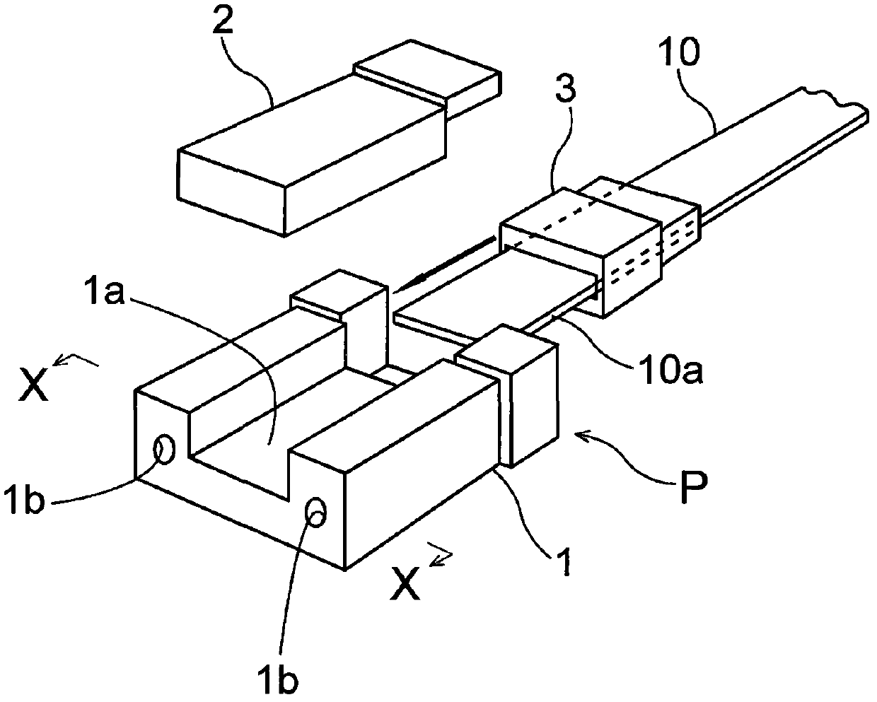
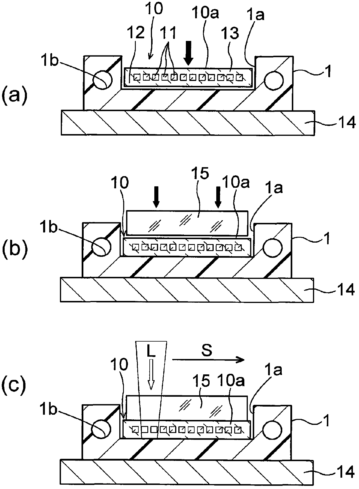
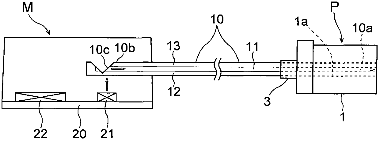

Image

  • Manufacturing method for an optical connector
  • Manufacturing method for an optical connector
  • Manufacturing method for an optical connector

Examples


Embodiment

[0049] Next, Examples will be described with reference to Comparative Examples. However, the present invention is not limited to the following examples.

[0050] In this embodiment, a polymer optical waveguide is fabricated by photolithography, and one end of the polymer optical waveguide is fixed to a commercially available PMT connector using a near-infrared laser. In addition, when using the same optical waveguide to fabricate the optical connector of the comparative example in which the end of the optical waveguide is fixed to the PMT connector with an adhesive, the insertion loss and The insertion loss "after mounting the joint" (after performing grinding in the comparative example) was compared. In addition, the measurement of insertion loss was performed in accordance with Japanese Industrial Standard JIS C 5961 "Test methods for optical fiber connectors".

[0051] Before proceeding to the examples, first, an optical waveguide for a test was fabricated.

[0052] Fa...


PUM


Abstract

Provided is a cost-effective manufacturing method for an optical connector, which enables an optical waveguide to be fixed to a ferrule easily in a short period of time. A manufacturing method for an optical connector includes: fitting an end portion of a transparent optical waveguide into an optical waveguide fitting groove of an optical connection ferrule made of a resin; and fusing and fixing the end portion of the transparent optical waveguide to the optical connection ferrule by applying a laser beam having a predetermined wavelength downward from above the optical waveguide fitting groove toward the transparent optical waveguide, so that the laser beam reaches a bottom surface of the optical waveguide fitting groove.

Description

technical field [0001] The present invention relates to a method of manufacturing an optical connector, and more particularly to a method of manufacturing an optical connector integrally mounted with a connector such as a PMT connector (Ferrule) for optical connection at the front end of an optical waveguide. Background technique [0002] In recent years, due to the integration and scale-up of electronic equipment, it is often used for the heat dissipation of electrical wiring such as the connection between boards (Boards) in the equipment and the connection between chips on the board and the heat dissipation of the electrical wiring. Power consumption becomes a problem. Therefore, an optical wiring (optical interconnection) technology has been developed in which the above-mentioned electric wiring is replaced with a light-weight, low-heat-emitting flexible polymer optical waveguide (see Patent Documents 1 and 2). [0003] In this optical wiring, an optical connector (optic...

Claims


Application Information

Patent Timeline
Patent Type & Authority Applications(China)
IPC IPC(8): G02B6/38G02B6/13
CPCG02B6/3855G02B6/3885G02B6/4214G02B6/4246G02B6/4249G02B6/4292
Inventor 长藤昭子松尾直之下田麻由
Owner NITTO DENKO CORP
Why Eureka
Eureka Blog
Learn More