
Electronic timepiece and reception control method for an electronic timepiece

An electronic clock and receiving control technology, applied to radio-controlled timers, clocks, electronic timers, etc., can solve problems such as load changes

Active Publication Date: 2012-08-15
SEIKO EPSON CORP
View PDF5 Cites 11 Cited by
  • Summary
  • Abstract
  • Description
  • Claims
  • Application Information

AI Technical Summary

Problems solved by technology

Therefore, when using an IC with low computing power, the load becomes heavy

Method used


Image

  • Electronic timepiece and reception control method for an electronic timepiece
  • Electronic timepiece and reception control method for an electronic timepiece
  • Electronic timepiece and reception control method for an electronic timepiece

Examples


no. 1 Embodiment approach

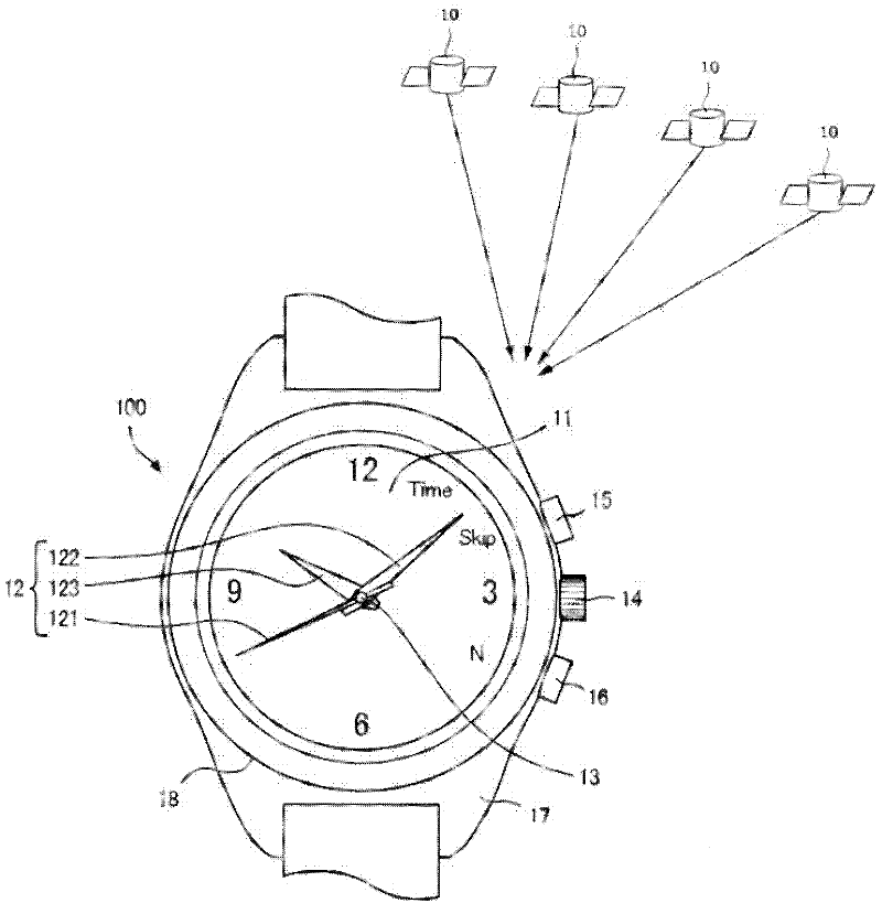
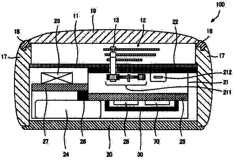
[0033] figure 1 It is a plan view of the electronic timepiece 100 according to the first embodiment of the present invention, figure 2 is a partial cross-sectional view of the electronic timepiece 100 . according to figure 1 It can be seen that the electronic timepiece 100 is a wristwatch worn on the user's wrist, has a dial 11 and hands 12, and measures the time and displays it on the surface. Most of the dial 11 is formed of a non-metallic material (for example, plastic or glass) that easily transmits light and microwaves in the 1.5 GHz band. The pointer 12 is provided on the front side of the dial 11 , includes a second hand 121 , a minute hand 122 , and an hour hand 123 that rotate around a rotating shaft 13 , and is driven by a stepping motor via gears.

[0034] In the electronic timepiece 100 , processes corresponding to manual operations of the crown 14 , push button 15 , and push button 16 are executed. Specifically, when the crown 14 is operated, manual correctio...

no. 2 Embodiment approach

[0114] Figure 10 It is a flowchart showing reception control processing according to the second embodiment of the present invention. right with Figure 9 Processes that are the same as those in the first embodiment shown are assigned the same reference numerals and description thereof will be omitted.

[0115] In the leap second reception timing table of this embodiment, the UTC offset is assumed to be 15 seconds, and the UTC-based reception start time obtained by subtracting the UTC offset from the GPS time is represented. In addition, in the second embodiment, the Figure 9 The processing of S0 shown, therefore, does not generate the reference time. Therefore, in S1 and S2, the internal time becomes the object of comparison. Also, in this embodiment, Figure 8 The table shown in (A) associates five patterns of minutes and seconds of leap second information reception timing using "hour" from 0:00 to 23:00 and "week number" from Sunday to Saturday.

[0116] However, for...


PUM


Abstract

An electronic timepiece can easily acquire a leap second information reception time with minimal processor load. A first table groups leap second information reception times expressed by hour, minute, second, and day values into plural minute-second patterns of minute-second combinations that are common to plural hours, and relates numbers identifying these minute-second patterns to the day and hour values. The minute-second combinations are grouped by number in a second table. The number corresponding to the day and hour of the internal time is found from the first table (S1). A minute-second combination that is later than the internal time is found from the minute-second combinations corresponding to the acquired number (S2). And leap second reception time is calculated. If the resulting leap second reception time matches the internal time is determined (S9) . If the times match, the leap second information is received (S10, S11).

Description

technical field [0001] The present invention relates to an electronic timepiece for obtaining the current date and time by receiving satellite signals transmitted from position information satellites such as GPS satellites, and a reception control method for the electronic timepiece. Background technique [0002] Patent Document 1 discloses a leap second correction method of obtaining subframe and page identification information from navigation data, and calculating the reception timing of leap second correction data based on the subframe and page identification information. In this leap second correction method, the calculated reception timing of the leap second is stored in the storage unit. [0003] Patent Document 1: Japanese Patent Laid-Open No. 2008-145287 [0004] However, in the method described in Patent Document 1, the page number and subframe in which the information on the leap second is described, and the page number and subframe obtained by GPS measurement are...

Claims


Application Information

Patent Timeline
Patent Type & Authority Applications(China)
IPC IPC(8): G04G5/00G04G7/02G04R20/06
CPCG04R20/06
Inventor 秋山利一吴栽官
Owner SEIKO EPSON CORP
Learn More