X-Ray CT device

An X-ray and irradiation field technology, applied in X-ray tubes, instruments for radiological diagnosis, medical science, etc., can solve the problems of reduced accuracy of focus position estimation, focus estimation, etc., and achieve the effect of suppressing artifacts

Active Publication Date: 2012-08-15
HITACHI HEALTHCARE MFG LTD
View PDF6 Cites 14 Cited by
  • Summary
  • Abstract
  • Description
  • Claims
  • Application Information

AI Technical Summary

Problems solved by technology

Therefore, the focal point cannot be estimated in consideration of the entire amount of thermal elongation caused by the obtained X-ray irradiation, and there is a problem that the estimation accuracy of the focal point position decreases.

Method used


Image

  • X-Ray CT device
  • X-Ray CT device
  • X-Ray CT device

Examples


no. 1 approach

[0049] The present embodiment is an X-ray CT apparatus used in the medical field as an example, below, use Figure 1 to Figure 14 Be explained.

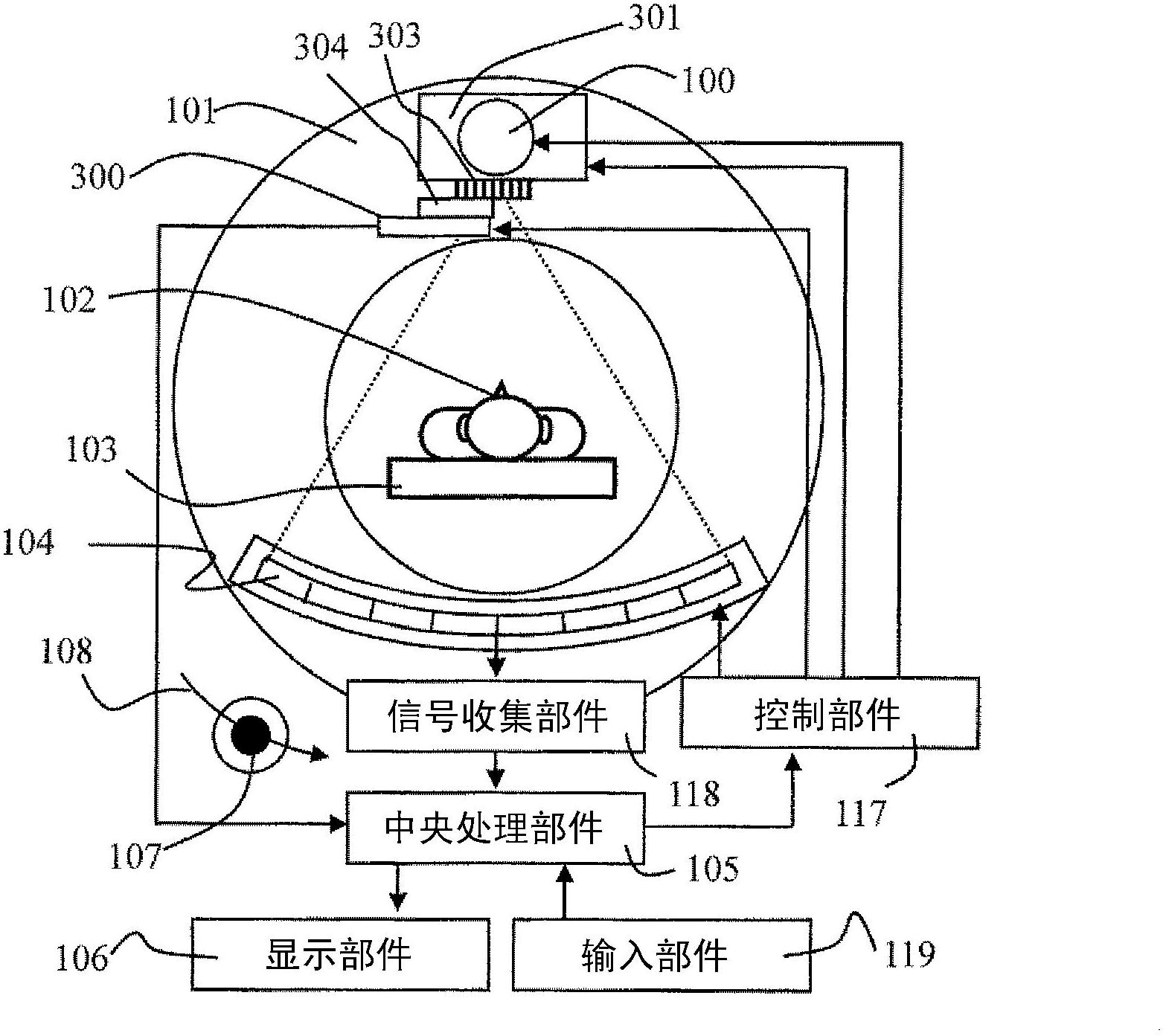
[0050] use figure 1 The outline of the X-ray CT apparatus of this embodiment will be described. The X-ray CT apparatus of the present embodiment is composed of the following components: X-ray source 100, X-ray tube moving part 301, X-ray collimator 303, X-ray detector 104, slit 304 for measuring the focal position and a slit for measuring the focal position. The detector 300 consists of a focus position detection unit, a signal collection unit 118 , a central processing unit 105 , a display device 106 , an input unit 119 , a control unit 117 , a gantry rotating unit 101 , and a bed plate 103 . A plurality of X-ray detectors 104 are arranged in an arc shape approximately centered on the X-ray source 100 , and are mounted on the gantry rotating unit 101 together with the X-ray source 100 . The following program is stored in the cen...

no. 2 approach

[0148] In the X-ray CT apparatus of this embodiment, for the movement of the X-ray irradiation field, instead of moving the X-ray tube 100 to control the focus position, the X-ray collimator 303 for limiting the X-ray irradiation field is controlled according to the change of the focus position. , and thus differs from the first embodiment in that a change in the irradiation field to the X-ray detector 104 is suppressed. use Figure 15 and Figure 16 An example of the X-ray CT apparatus of this embodiment will be described.

[0149] Such as Figure 15 As shown, this X-ray CT apparatus has an X-ray collimator moving unit 302 that moves the X-ray collimator 303 in the slice direction 107 . The central processing unit 105 calculates the movement amount according to the focus movement distance X, and the movement can be realized by controlling the X-ray collimator moving unit 302 through the control unit 117 .

[0150] use Figure 16 , an example of this control method and th...

no. 3 approach

[0156] The X-ray CT apparatus of the third embodiment does not control the X-ray tube 100 according to the change of the focus position for the movement of the X-ray irradiation field, but controls the movement of the X-ray detector 104 so that the X-ray It is different from the first embodiment in that the irradiation field of the detector 104 does not change. use Figure 17 to Figure 19 An example of the X-ray CT apparatus of this embodiment will be described.

[0157] Such as Figure 17 As shown, the present X-ray CT apparatus has an X-ray detector moving unit 200 that moves the X-ray detector 104 in the slice direction 107 . The central processing unit 105 calculates the movement amount based on the focal point movement distance X, and the movement can be realized by controlling the X-ray detector moving unit 200 through the control unit 117 .

[0158] Next, use Figure 18 , an example of this control method and the calculation method of the movement amount will be des...


PUM


Abstract

In order to eliminate and suppress image quality degradation including the occurrence of an artifact and the deterioration of quantitative performance caused by a focal shift, without delaying a photographing timing by accurately estimating the shift amount of a focal position without x-ray irradiation for detecting the focal position and by changing the x-ray irradiation field, disclosed is an X-ray CT device provided with: an X-ray generation means (100); an X-ray detection means (104); an X-ray collimator means (303); a reconstruction processing means (105); an irradiation field change drive means (200, 301, 302) which controls and moves at least one of the X-ray generation means (100), the X-ray detection means, and the X-ray collimator means (303); and a shift amount calculation means (105) which estimates the focal position of the X-ray generation means at an estimation time (S2, S4), and using the result of the estimation, calculates the shift amount, which is needed to keep the X-ray incident position in the X-ray detection means constant, of the irradiation field change drive means (S6). When a predetermined time has passed since a time at which the focal position is estimated in the most recent past, or when a photographing start instruction signal is inputted, the shift amount calculation means calculates the shift amount (S8), and the irradiation field change drive means performs the control and shift corresponding to the shift amount before the next estimation time or X-ray irradiation (S9).

Description

technical field [0001] The present invention relates to an X-ray CT device, in particular to an X-ray CT device capable of correcting changes in the focus position of an X-ray tube. Background technique [0002] The X-ray CT apparatus calculates the X-ray absorption coefficient based on the X-ray transmission images (hereinafter, referred to as projection data) of the subject captured from multiple directions, and obtains the tomographic image of the subject (hereinafter referred to as reconstruction data). image) device. It is widely used in the fields of medical treatment and non-destructive inspection. In recent years, especially in the medical field, high-speed rotation drive and multi-level X-ray detectors in the direction of the rotation axis have been promoted. Accordingly, it is possible to image the entire moving organ such as the heart without blurring. [0003] An X-ray tube used as an X-ray source in such an X-ray CT apparatus, for example, as described in Pate...

Claims


Application Information

Patent Timeline
Patent Type & Authority Applications(China)
IPC IPC(8): A61B6/03
CPCA61B6/4488A61B6/032A61B6/482A61B6/547A61B6/583H01J35/26
Inventor 昆野康隆石川卓
Owner HITACHI HEALTHCARE MFG LTD
Why Eureka
Try Eureka