
Bevel cutting device of plasma cutting machine

A plasma cutting machine and groove cutting technology, which is applied in plasma welding equipment, welding equipment, metal processing equipment, etc., can solve the problems of heavy weight, unsatisfactory assembly accuracy, and large structure, so as to improve quality and stability. performance, reduced size and weight, and strong impact resistance

Inactive Publication Date: 2012-08-22
WUHAN FARLEYLASERLAB CUTTING SYST ENG
View PDF6 Cites 0 Cited by
  • Summary
  • Abstract
  • Description
  • Claims
  • Application Information

AI Technical Summary

Problems solved by technology

[0003] For a long time, the processing of plate grooves in my country has been completed by mechanical processing and gouging, or by CNC plasma linear cutting and blanking, and then secondary processing of the grooves with other equipment, which has seriously affected the production efficiency and progress of enterprises, and cannot adapt Modern fast-paced and efficient bevel cutting requirements
[0004] At present, in terms of plasma bevel cutting, only a few multinational companies have mature beveling technology, and they have adopted a strategy of high price and high profit to restrict the domestic plasma bevel cutting market; among the bevel cutting devices developed and produced by domestic manufacturers , the ubiquitous structure is huge, its own quality is too heavy, or the structure is too complex, the rigidity is poor, the assembly accuracy cannot meet the requirements, and the cutting speed and quality cannot be guaranteed.
It can be said that the current domestic plasma bevel cutting devices are still unable to meet the user's requirements for high-quality, high-efficiency, and high-precision bevel cutting

Method used


Image

  • Bevel cutting device of plasma cutting machine
  • Bevel cutting device of plasma cutting machine
  • Bevel cutting device of plasma cutting machine

Examples


Embodiment Construction

[0021] The present invention will be further described below in conjunction with the accompanying drawings and specific embodiments, so that those skilled in the art can better understand the present invention and implement it, but the examples given are not intended to limit the present invention.

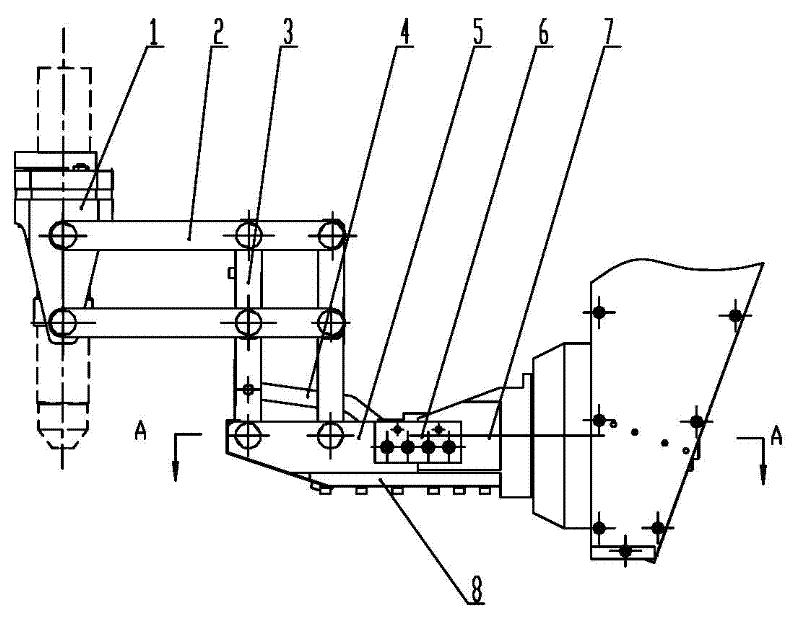
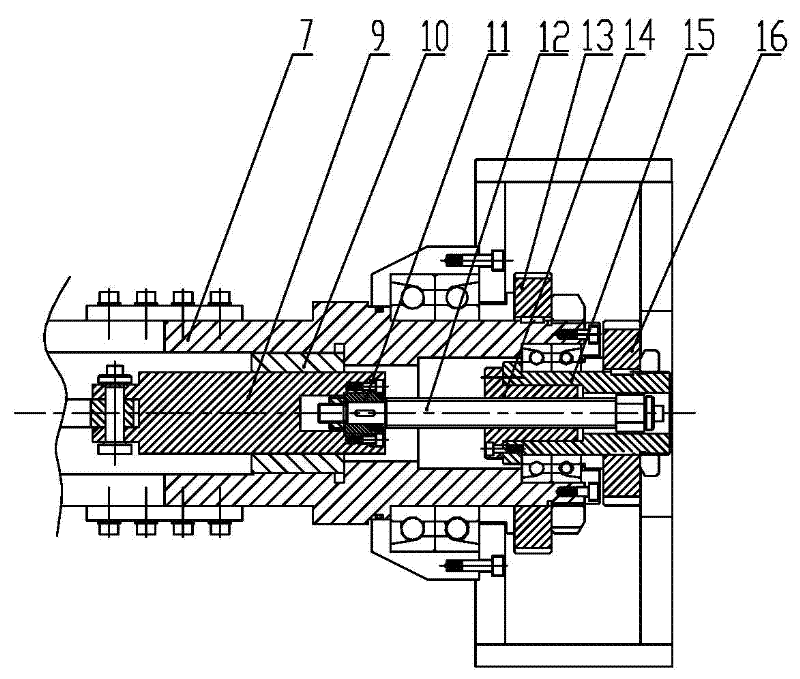
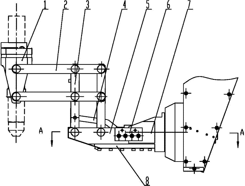
[0022] Such as figure 1 and figure 2 As shown, an embodiment of the ion cutting machine bevel cutting device of the present invention includes a gun body clamping linkage mechanism, a horizontal rotation mechanism and a longitudinal rotation mechanism, and the curved rod 4 of the gun body clamping linkage mechanism is connected to the longitudinal rotation mechanism The reciprocating shaft 9 of the mechanism is hinged, and the gun body clamping link mechanism is fixed with the rotary shaft 7 of the horizontal rotary mechanism through the fixed base plate 8 and the fixed seat 6, and the rotary shaft 7 is respectively connected with the fixed sleeve 10, Nut seat 15 is connected. ...


PUM


Abstract

The invention discloses a bevel cutting device of a plasma cutting machine. The bevel cutting device comprises a gun body clamping linkage mechanism, a transverse rotating mechanism and a longitudinal rotating mechanism, wherein a bent rod of the gun body clamping linkage mechanism is hinged with a reciprocating shaft of the longitudinal rotating mechanism, the gun body clamping linkage mechanism is fixed with a rotating shaft of the transverse rotating mechanism through a fixing bottom plate and a fixing seat, and the rotating shaft is respectively connected with a fixing sleeve and a nut seat of the longitudinal rotating mechanism. The bevel cutting device of the plasma cutting machine has the advantages of stability and reliability, simple structure, light weight and good rigidity, and the cutting accuracy, surface machining quality and production efficiency are greatly improved.

Description

technical field [0001] The invention relates to the technical field of plasma composite processing, in particular to a bevel cutting device for a plasma cutting machine. Background technique [0002] In recent years, the development of CNC plasma cutting machines in China is obvious to all, but the development of CNC plasma sheet bevel cutting is still relatively slow, especially compared with foreign counterparts, there is still a big gap. my country's CNC plasma sheet bevel cutting equipment is far behind developed countries in terms of function, quality and efficiency. [0003] For a long time, the processing of plate grooves in my country has been completed by machining and gouging, or by CNC plasma linear cutting and blanking, and then secondary processing of the grooves with other equipment, which has seriously affected the production efficiency and progress of enterprises, and cannot adapt Modern fast-paced and efficient bevel cutting requirements. [0004] At presen...

Claims


Application Information

Patent Timeline
IPC IPC(8): B23K10/00
Inventor 熊衍军黄斅董结叶松平昝东山张金明孙勇
Owner WUHAN FARLEYLASERLAB CUTTING SYST ENG
Learn More