Accelerator pedal and brake pedal-based electrically driven automobile feedback brake control method

A technology of brake pedal and regenerative braking, which is applied in the direction of electric vehicles, electric braking systems, vehicle components, etc. Large braking force and other problems, to achieve the effect of ensuring ride comfort and braking safety, improving comfort, and changing smoothly

Active Publication Date: 2012-08-22
TSINGHUA UNIV
View PDF5 Cites 32 Cited by
  • Summary
  • Abstract
  • Description
  • Claims
  • Application Information

AI Technical Summary

Problems solved by technology

In the prior art, in the accelerator pedal feedback stage, the motor feedback braking force is mostly calculated with the vehicle speed as an independent variable, and the driver’s braking intention is not comprehensively judged, and the control logic is relatively simple; in the brake pedal feedback stage, most of them do not The hydraulic braking force is adjusted, but the motor braking force is directly superimposed on the hydraulic braking force. The motor braking force applied in this process is very small, which not only makes the energy recovery efficiency low, but also causes the total braking force of the car to be too large , does not match the driver's braking demand, resulting in poor braking comfort and driving feeling, and even in extreme cases, the wheels are more likely to lock up, which affects braking safety

Method used


Image

  • Accelerator pedal and brake pedal-based electrically driven automobile feedback brake control method
  • Accelerator pedal and brake pedal-based electrically driven automobile feedback brake control method
  • Accelerator pedal and brake pedal-based electrically driven automobile feedback brake control method

Examples


Embodiment Construction

[0014] The present invention will be described in detail below in conjunction with the accompanying drawings and embodiments.

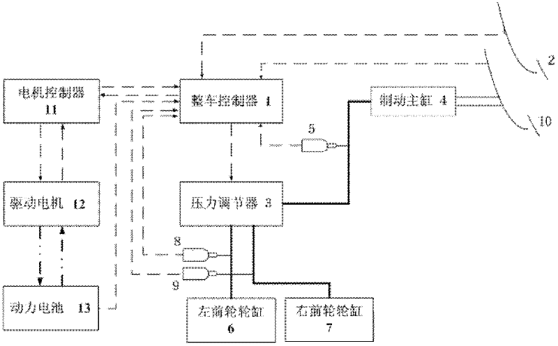
[0015] Such as figure 1 As shown, the regenerative braking control system for electric drive vehicles of the present invention includes a vehicle controller (VCU) 1; four wheel speed sensors (not shown) that are respectively arranged on each wheel; Displacement sensor on 2; a pressure regulator 3 arranged between the brake master cylinder and the brake wheel cylinder; a master cylinder pressure sensor 5 arranged at the outlet of the brake master cylinder 4; a pressure regulator 5 arranged at the front wheel cylinder The front wheel cylinder pressure sensor at the entrance, the front wheel cylinder pressure sensor includes the left front wheel cylinder pressure sensor 8 and the right front wheel cylinder pressure sensor 8 respectively arranged at the entrance of the left front wheel cylinder 6 and the right front wheel cylinder 7 A pressure sensor 9; ...


PUM


Abstract

The invention relates to an accelerator pedal and brake pedal-based electrically driven automobile feedback brake control method, which comprises the following steps of: (1) arranging an electrically driven automobile feedback brake control system comprising a vehicle controller, a wheel speed sensor, an accelerator pedal displacement sensor, a pressure regulator, a main cylinder pressure sensor, a front wheel cylinder pressure sensor and a brake pedal switch; (2) judging, by the vehicle controller, braking intention of a driver according to a current operation state of the automobile, dividing brake feedback control into three stages, i.e., an accelerator pedal-based feedback control stage, a brake pedal-based feedback control stage and a control stage of a switching process from accelerator pedal-based feedback to brake pedal-based feedback; and (3) calculating, by the electrically driven automobile feedback brake control system, motor feedback braking force of the three feedback control stages respectively, thereby keeping the vehicle total brake force consistent with the driver brake requirement. The accelerator pedal and brake pedal-based electrically driven automobile feedback brake control method can be widely applied to electrically driven automobile feedback brake control of a pure electric vehicle, a hybrid electric vehicle and the like.

Description

technical field [0001] The invention relates to an automobile regenerative braking control method, in particular to an electric drive automobile regenerative braking control method based on an accelerator pedal and a brake pedal, which is suitable for a pure electric vehicle or a hybrid electric vehicle. Background technique [0002] Due to the aggravation of energy problems and environmental pollution problems, it is of great significance to study and apply electric vehicles. As a key technology for electric vehicles to save energy, reduce emissions and reduce energy consumption, braking energy recovery technology is currently widely used by major electric vehicle manufacturers at home and abroad. The voltage is reversed to make it work in the power generation state, and the vehicle is braked by the feedback braking force of the drive motor. The energy fed back during the braking process will be stored in the battery in the form of electric energy, so that the vehicle can b...

Claims


Application Information

Patent Timeline
Patent Type & Authority Applications(China)
IPC IPC(8): B60L7/18B60L7/26
Inventor 张俊智岳小伟吕辰苟晋芳何承坤
Owner TSINGHUA UNIV
Why Eureka
Try Eureka