Vibratory spiral fluidized horizontal shell-and-tube heat exchanger

A horizontal tube-and-vibration-spiral technology, applied in heat exchanger types, indirect heat exchangers, fixed tubular conduit components, etc., can solve the problems of difficult concentration adjustment operation technology and difficulty in adjusting the range to meet engineering requirements, etc. achieve effective cleaning

Inactive Publication Date: 2012-08-22
俞天翔
View PDF5 Cites 15 Cited by
  • Summary
  • Abstract
  • Description
  • Claims
  • Application Information

AI Technical Summary

Problems solved by technology

[0005] Third, there are also obvious shortcomings in particle recycling and concentration regulation
One is that it is necessary to independently set up a fluidized fluidized ball external "circulation tank" outside the main equipment, which will inevitably increase the number of connected pipelines and valves; the other is for heat transfer that needs to be adjusted for basic parameters such as tube-side flow Equipment, the structure of "fluidized liquid preparation pipe in the lower part of the circulation tank" is technically difficult to adjust the concentration, and the adjustment range is often difficult to meet the engineering requirements

Method used


Image

  • Vibratory spiral fluidized horizontal shell-and-tube heat exchanger
  • Vibratory spiral fluidized horizontal shell-and-tube heat exchanger
  • Vibratory spiral fluidized horizontal shell-and-tube heat exchanger

Examples


Embodiment Construction

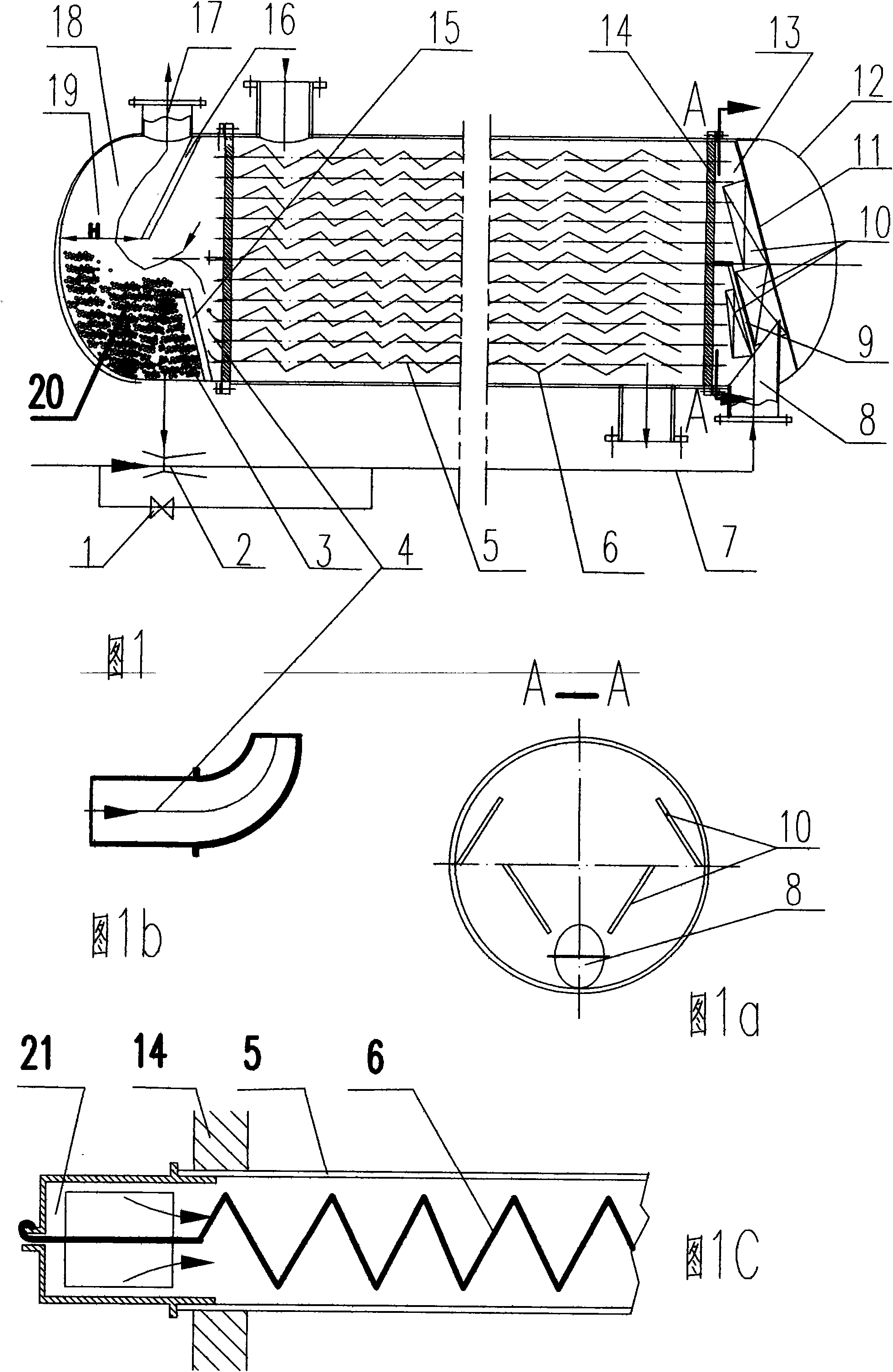
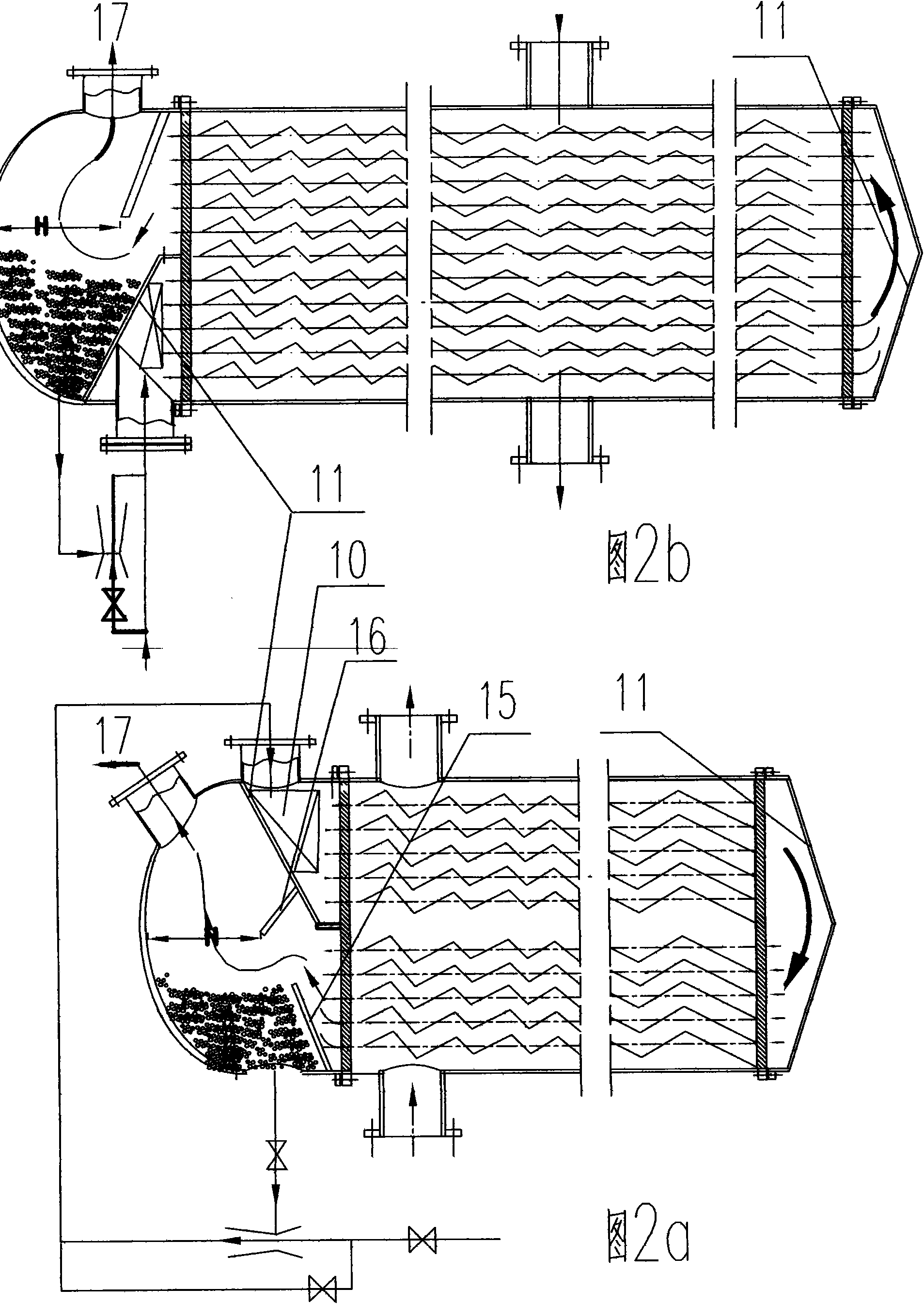
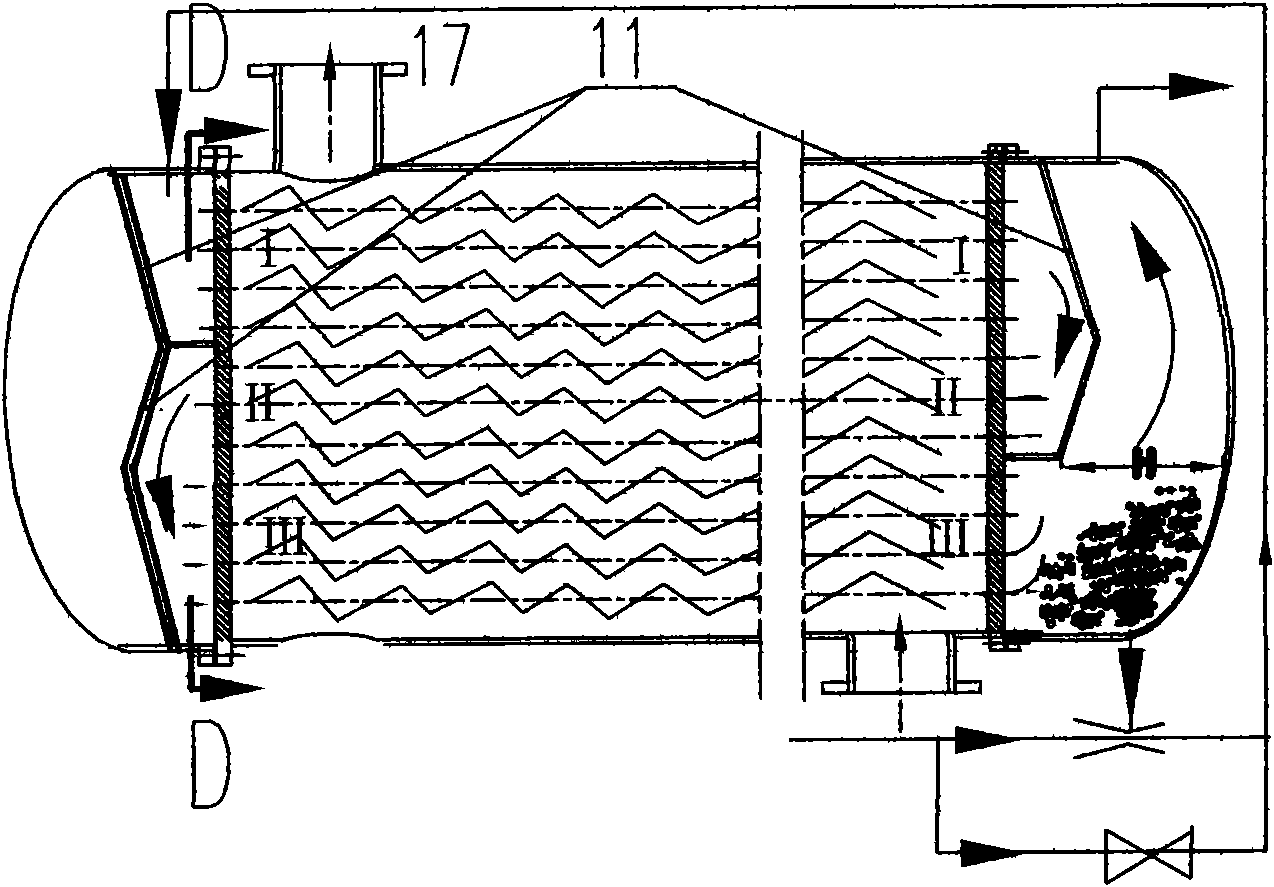
[0020] Attached below figure 1 , 1a , 1b, 1c, 2a, 2b, 3a, 3b, 4a, 4b, 4c, the present invention is described in further detail.

[0021] In the figure, 1 regulating valve 2 Venturi 3 fluidizing ball 4 accelerating elbow 5 heat exchange tube 6 steel wire helix 7 inlet pipeline 8 inlet pipe 9 partition uniform distribution plate 10 radial uniform distribution plate 11 uniform distribution cover 12 pressure bearing end Cover 13 Evenly distributed tube box 14 Tube plate 15 Circulation tank partition 16 Sand plate 17 Outlet tube 18 Outlet tube box 19 Maximum cross section 20 Fluidized ball circulation tank 21 Fixing frame

[0022] A vibrating spiral fluidized horizontal tube-and-tube heat exchanger, the main components of which are a uniformly distributed tube box 13, an outlet tube box 18, a heat exchange tube 5, a steel wire helix 6, a fluidizing ball 3, a Venturi 2, and a regulating valve 1. 7 inlet pipes and 8 outlet pipes. Each heat exchange tube 5 is provided with a steel ...


PUM


Abstract

The invention relates to a vibratory spiral fluidized horizontal shell-and-tube heat exchanger. Structures such as evenly distributed headers are used for improving the uniformity of fluidizing balls to enter heat exchange tubes. The clearance between the outer diameter of a steel wire spiral line and a pipe inner wall is more than two times of the diameter of the fluidizing ball. Dead zones during cleaning of fluidizing ball scale are eliminated. During operation, the fluidizing balls make spiral line motion under the push of a spiral flow, the centrifugal force of the fluidizing balls is naturally concentrated on the tube inner wall and pressure required for cleaning hard scale is produced. Sliding component velocity of the fluidizing balls on the tube inner wall takes an effect of automatically cleaning the hard scale. The fluidizing balls roll at high speed and violently and transversely agitate a boundary layer, the supersaturation degree of a stagnant layer is greatly reduced, the generation of hard scale is avoided or remarkably relieved and a more valuable antiscale effect is obtained. Since the inlet end of the steel wire spiral line which is arranged in each heat exchange tube is fixed and the tail end of the steel wire spiral line is free, the situation that the steel wire spiral line wears the tube inner wall is avoided. Therefore, the heat exchanger is suitable for all situations that hard scale is formed in horizontal shell-and-tube heat exchangers with all kinds of structures.

Description

technical field [0001] The patent of the present invention relates to a vibrating spiral fluidized horizontal tube heat exchanger, which relates to online automatic cleaning of hard scale in the tube of the horizontal tube heat exchanger and enhanced heat transfer and energy saving. It is suitable for various shell and tube heat exchangers with horizontal heat exchange tubes, such as heat exchangers without phase change, condensers (including water-cooled condensers of vacuum equipment attached to steam turbines), evaporators, etc. Background technique [0002] The tube-side fluidization technology of the tube-and-tube heat exchanger, the earlier patent EP262725 and the Chinese patent ZL91106682.9, etc., have the dual functions of automatically cleaning the dirt in the tube and enhancing efficient heat transfer. However, they can only be applied to vertical equipment, and they are only vertical equipment with upward flow; while 90% of the shell and tube heat exchangers are h...

Claims


Application Information

Patent Timeline
Patent Type & Authority Applications(China)
IPC IPC(8): F28D7/16F28F13/00F28F13/02F28G1/12F28G13/00
Inventor 俞天翔
Owner 俞天翔
Why Eureka
Try Eureka