
Device and method for measuring size and roundness of tiny round hole at same time

A round hole, tiny technology, applied in the field of measurement of tiny round holes, can solve the problems of not being able to measure the roundness at the same time, difficult to accurately measure the size of the microhole, and unable to find the center point, etc.

Inactive Publication Date: 2014-06-25
XIAMEN UNIV OF TECH
View PDF8 Cites 0 Cited by
  • Summary
  • Abstract
  • Description
  • Claims
  • Application Information

AI Technical Summary

Problems solved by technology

The existing non-contact testing devices or instruments for tiny round holes, based on the diffraction method, can only measure their size, but cannot measure their roundness at the same time; The light hole that exits will also become smaller, the light passing through the microhole will become weaker, and the measurement accuracy of its size and roundness will become lower
[0003] Chinese document CN 02137742.1 relates to an automatic measurement method and device for micropores. The steps of the method are as follows: the CCD camera inputs the enlarged image of the micropores through the microscope into the computer; the area method is used to filter the micropore images to find the corresponding Store the coordinates of the boundary points of the micropores in the linked list, calculate the coordinates of the center point of the micropores, find the maximum value of the aperture in the direction of 0 to 180 degrees, select the maximum and minimum values, and obtain the average value of the aperture and the roundness error However, this measurement method cannot find the center point, and the light source used is an ordinary light source, and the micropore size is extremely small. It is difficult to accurately measure the micropore size only by taking pictures of the microholes with a camera and enlarging the image.

Method used


Image

  • Device and method for measuring size and roundness of tiny round hole at same time
  • Device and method for measuring size and roundness of tiny round hole at same time
  • Device and method for measuring size and roundness of tiny round hole at same time

Examples


Embodiment

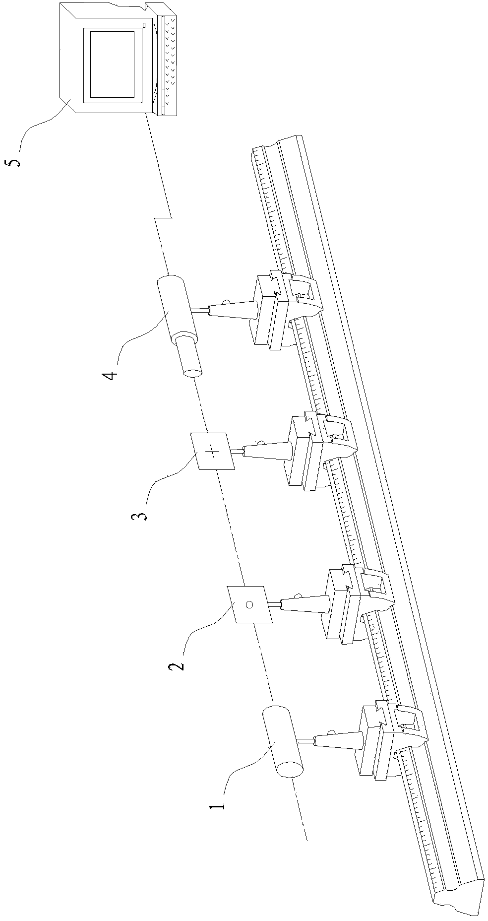
[0029] Example: see figure 1 , a device for simultaneously measuring the size and roundness of tiny circular holes, comprising a He-Ne laser 1, a circular hole to be measured and a holder 2, a frosted glass receiving screen with a mark 3, an information collection device 4, and an information processing device 5,

[0030] Among them, the He-Ne laser 1, the circular hole to be measured and the holder 2, the glass receiving screen 3 with the logo and the information collection device 4 are carried by the two-dimensional adjustable device and placed on the optical platform, in which the tiny circle to be measured is clamped. The hole is a precision two-dimensional adjustable device, through adjustment to ensure that their optical axis (or center) is basically on a straight line, the surface of the measured round hole, the holder and the glass receiving screen with the mark are parallel and perpendicular to the above-mentioned straight line, the data Through precise adjustment and...


PUM


Abstract

The invention discloses a device and a method for measuring the size and roundness of a tiny round hole at the same time. The device comprises a He-Ne laser device, a measured round hole, a clamp device, a frosted glass receiving screen with a mark, an information acquisition device and an information processing device. The measurement of the device is based on the laser Fraunhofer diffraction measurement principle, the frosted glass with a special mark is placed in a diffraction field as a diffraction pattern receiving screen, an area array CCD (charge coupled device) acquires the diffraction pattern containing the special mark on the receiving screen, and the specially-developed software on a computer finishes the calibration and the diffraction pattern information acquisition so as to automatically measure the size and roundness of the tiny round hole at the same time. The measurement range (the diameter of the tiny round hole) of the device is 0.005-0.5mm.

Description

technical field [0001] The invention discloses a device and method for simultaneously measuring the size and roundness of tiny round holes, and belongs to the technical field of measuring tiny round holes according to the International Patent Classification (IPC). Background technique [0002] The size (diameter) and roundness of tiny circular holes are the characteristic parameters of circular holes that are of great concern in precision machining. The existing non-contact testing devices or instruments for tiny round holes, based on the diffraction method, can only measure their size, but cannot measure their roundness at the same time; The light hole that exits will also become smaller, the light passing through the microhole will become weaker, and the measurement accuracy of its size and roundness will become lower. [0003] Chinese document CN 02137742.1 relates to an automatic measurement method and device for micropores. The steps of the method are as follows: the C...

Claims


Application Information

Patent Timeline
Patent Type & Authority Patents(China)
IPC IPC(8): G01B11/08G01B11/24
Inventor 徐代升朱文章甘亮勤林洪沂
Owner XIAMEN UNIV OF TECH
Learn More