Eureka AIR delivers breakthrough ideas for toughest innovation challenges, trusted by R&D personnel around the world.

Coordinate measuring machine based on electromagnetic induction limiting

A three-coordinate tester and electromagnetic induction technology, applied in instruments, measuring devices, etc., can solve the problems affecting the accuracy of the three-coordinate tester and the measurement accuracy of the workpiece to be measured, etc., to achieve sensitive response, improve test accuracy, Easy-to-use effects

Inactive Publication Date: 2012-08-22
SUZHOU EASSON OPTOELECTRONICS
View PDF4 Cites 1 Cited by
  • Summary
  • Abstract
  • Description
  • Claims
  • Application Information

AI Technical Summary

Problems solved by technology

[0002] The three-coordinate tester has a sliding device that moves in three mutually perpendicular directions. When measuring the workpiece, the position of the sliding device must be continuously adjusted. The existing technology for limiting the sliding device is generally controlled by a proximity switch. This requires the sliding device to touch a certain fixed device. Even a small contact collision will seriously affect the accuracy of the three-coordinate tester, and then affect the accuracy of the measurement of the workpiece to be measured.

Method used


Image

  • Coordinate measuring machine based on electromagnetic induction limiting
  • Coordinate measuring machine based on electromagnetic induction limiting

Examples


Embodiment Construction

[0012] The present invention will be specifically introduced below in conjunction with the accompanying drawings and specific embodiments.

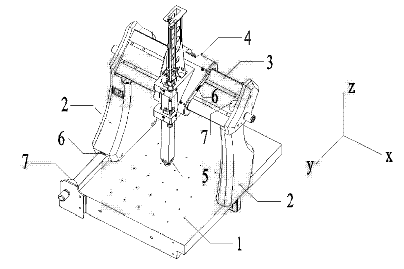
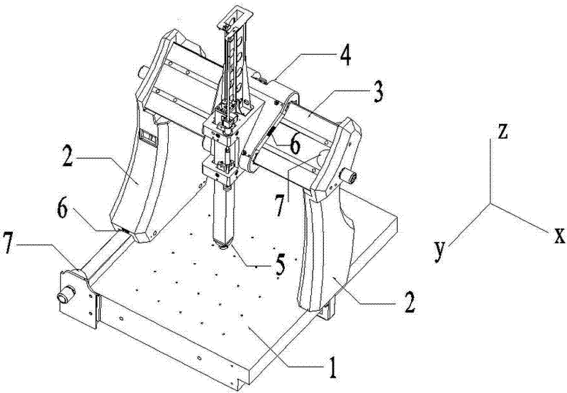
[0013] refer to figure 1 , the electromagnetic induction limit three-coordinate tester of the present invention includes: a base 1, a vertical arm 2, a horizontal bridge 3, a slider group 4, a measuring probe group 5, a driving device (not shown), a magnetic detection device 6 and magnetic limiter 7.

[0014] The base 1 is used to provide a platform for placing the object to be tested; the vertical arm 2 is used to slide above the base 1 along the first direction y; the two ends of the horizontal bridge 3 are respectively fixedly connected to the two vertical arms 2, and the two A vertical arm 2 plays the role of supporting, fixing and driving the horizontal bridge 3 to move; the slider group 4 is used to slide along the second direction x on the horizontal bridge 3, and the measurement probe group 5 is installed on the slider group 4, ...


PUM


Abstract

The invention discloses a coordinate measuring machine based on electromagnetic induction limiting, which comprises a base which is used for providing a platform for placing an object to be measured, two vertical arms which are used for sliding above the base, a horizontal bridge which is fixedly connected with the two vertical arms, a sliding block unit which slides on the horizontal bridge and a measuring probe unit which is installed on the sliding block unit and can move relative the sliding block unit. A first direction, a second direction and a third direction form three axes which are perpendicular to one another in a rectangular coordinate system. The vertical arms and the sliding block unit are provided with driving devices and magnetic detection devices. The base and the horizontal bridge are provided with magnetic limiting pieces which feed back signals to the magnetic detection devices through the magnetism of the magnetic limiting pieces and are used for limiting the positions of the vertical arms and the sliding block unit. The coordinate measuring machine based on electromagnetic induction limiting has the beneficial effects that the positions of the vertical arms and the sliding block unit on the base and the horizontal bridge are limited by using the principle of magnetic induction, the unnecessary contact collision is avoided, the relative stability of the vertical arms and the sliding block unit is guaranteed and the measuring accuracy of the coordinate measuring machine is improved; and the response sensitivity is high and the coordinate measuring machine is convenient to operate.

Description

technical field [0001] The invention relates to a three-coordinate tester, in particular to a three-coordinate tester for electromagnetic induction limit. Background technique [0002] The three-coordinate tester has a sliding device that moves in three mutually perpendicular directions. When measuring the workpiece, the position of the sliding device must be continuously adjusted. The existing technology for limiting the sliding device is generally controlled by a proximity switch. This requires the sliding device to touch a certain fixed device. Even a small contact collision will seriously affect the accuracy of the three-coordinate tester, and then affect the accuracy of the measurement of the workpiece to be tested. Contents of the invention [0003] In order to solve the deficiencies of the prior art, the object of the present invention is to provide a three-coordinate tester which utilizes electromagnetic induction to smoothly limit the position of the sliding devic...

Claims


Application Information

Patent Timeline
Patent Type & Authority Applications(China)
IPC IPC(8): G01B21/00
Inventor 陆庆年
Owner SUZHOU EASSON OPTOELECTRONICS
Why Eureka
Eureka Blog
Learn More