Supercharge Your Innovation With Domain-Expert AI Agents!

Projection lens and projection apparatus

A technology of projection lens and projection device, which is applied in the direction of projection device, condenser lens, optics, etc. It can solve the problems of difficult reduction in the volume of the optical system, the decrease of the brightness of the image screen, and the large offset of the light valve, so as to achieve good imaging quality and reduce the size , the effect of small volume

Active Publication Date: 2012-08-22
YOUNG OPTICS
View PDF6 Cites 8 Cited by
  • Summary
  • Abstract
  • Description
  • Claims
  • Application Information

AI Technical Summary

Problems solved by technology

When the offset of the light valve is above 100%, it means that the offset of the light valve relative to the projection lens is relatively large, so it is easy to cause the volume of the entire optical system to be difficult to reduce
If in order to reduce the volume of the optical system so that the projection system can be applied in portable electronic devices, the part on the other side of the offset of the projection lens relative to the light valve can be trimmed, but this is easy to cause The effective area (clear aperture) of the image beam is greatly cut off, resulting in a significant decrease in the brightness of the image screen

Method used


Image

  • Projection lens and projection apparatus
  • Projection lens and projection apparatus
  • Projection lens and projection apparatus

Examples


Embodiment Construction

[0019] The aforementioned and other technical content, features and effects of the present invention will be clearly presented in the following detailed description of preferred embodiments with reference to the drawings. The directional terms mentioned in the following embodiments, such as: up, down, left, right, front or back, etc., are only referring to the directions of the drawings. Accordingly, the directional terms are used to illustrate and not to limit the invention.

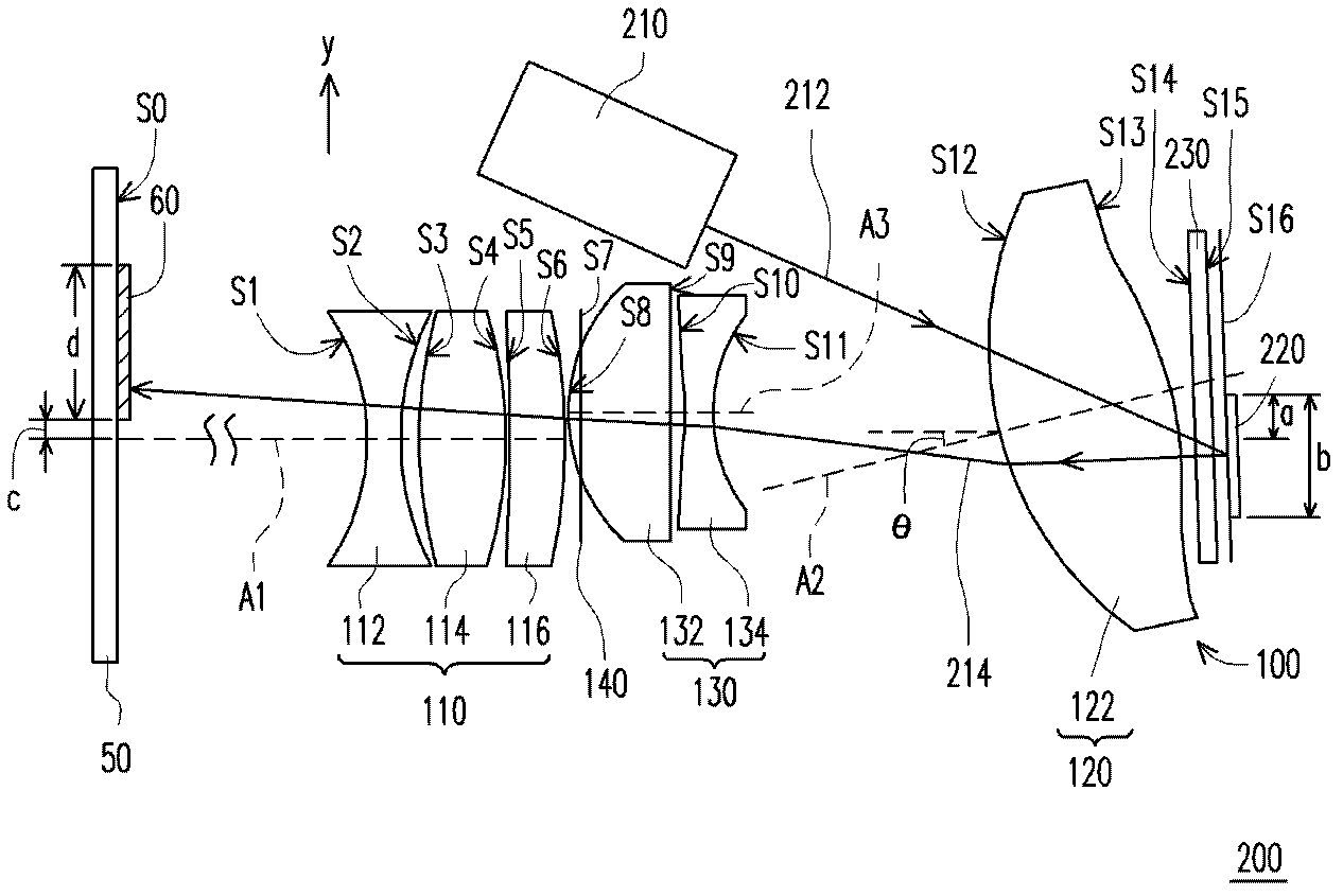
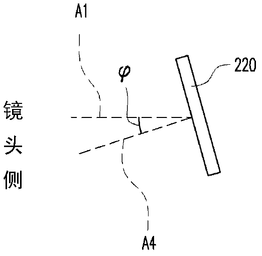
[0020] Figure 1A is a schematic diagram of a projection device according to an embodiment of the present invention, and Figure 1B draw Figure 1A Situations where the fourth optical axis of the light valve in is tilted with respect to the first optical axis. Please refer to Figure 1A and Figure 1B , the projection device 200 of this embodiment includes an illumination system 210 , a light valve 220 and a projection lens 100 . The illumination system 210 is used for providing an illumination beam ...


PUM


Abstract

A projection lens for projecting an image beam is provided. The image beam is converted by a light valve from an illumination beam irradiating the light valve. The projection lens includes a first lens group, a second lens group, and a third lens group. The first lens group is disposed on a transmission path of the image beam, and has a first optical axis. The second lens group is disposed on both a transmission path of the illumination beam and the transmission path of the image beam, and between the light valve and the first lens group. The second lens group has a second optical axis. The second optical axis is inclined with respect to the first optical axis. The third lens group is disposed on the transmission path of the image beam, and between the first lens group and the second lens group. A projection apparatus is also provided.

Description

technical field [0001] The invention relates to an optical element and a display device, and in particular to a projection lens and a projection device. Background technique [0002] Among various types of display devices, the projection device has the characteristic of being able to project a large-sized image frame several times larger than the surface area of ​​the device with a smaller device volume, so it has an irreplaceable advantage in the display field. Since the projection device images the image of the light valve on the screen through the projection lens, the image quality is greatly affected by the imaging quality of the projection lens. Therefore, the projection lens is a very important optical element in the projection device. [0003] Since the projection device is usually set on the desktop or hung upside down on the ceiling, the light valve of the projection device usually has an offset greater than 100% relative to the optical axis of the projection lens,...

Claims


Application Information

Patent Timeline
Patent Type & Authority Applications(China)
IPC IPC(8): G02B13/00G02B13/18G03B21/14G03B21/20G02B26/08
CPCG02B13/16G02B19/0047G02B19/0014
Inventor 王国权康尹豪谢启堂李嘉樟
Owner YOUNG OPTICS
Features
  • R&D
  • Intellectual Property
  • Life Sciences
  • Materials
  • Tech Scout
  • Unparalleled Data Quality
  • Higher Quality Content
  • 60% Fewer Hallucinations
Learn More