drill

A drill bit and plastic technology, applied in twist drills, drilling tool accessories, drilling/drilling equipment, etc., can solve the problem of high cost and achieve the effect of long service life, low wear and high surface quality

Inactive Publication Date: 2016-08-24
MAPAL FABRIK FUER PRAEZISIONSWERKZEUGE (DE)
View PDF11 Cites 0 Cited by
  • Summary
  • Abstract
  • Description
  • Claims
  • Application Information

AI Technical Summary

Problems solved by technology

The disadvantage is that the drilling results do not in all cases meet the requirements with regard to the surface quality of the borehole wall and the shape accuracy of the borehole and therefore require improvement
In addition, the outlay and thus the costs in the manufacture of drill bits are relatively high

Method used


Image

  • drill
  • drill
  • drill

Examples


Embodiment Construction

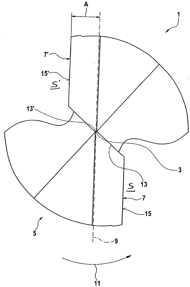
[0031] exist figure 1 A schematic top view of a first embodiment of the drill bit 1 is illustrated in . The viewing direction is from above towards the tip 3 of the drill 1 .

[0032] The drill 1 has a base body 5 on which a first main cutting edge 7 and a second main cutting edge 7' arranged centrally symmetrically with respect to the axis of rotation of the drill extending through the tip 3 are arranged. The two main cutting edges 7, 7' are arranged parallel to an imaginary straight line 9 extending through the axis of rotation and corresponding to the diameter line. The distance A between the straight line 9 and the main cutting edges 7, 7' is approximately 15% of the main hole diameter of the drill 1, respectively. The main borehole diameter is the diameter of the drill 1 measured radially between the points of the main cutting edges 7, 7' furthest from the axis of rotation, which lie in front of the straight line 9 in the direction of rotation of the drill 1 indicated b...


PUM

PropertyMeasurementUnit
widthaaaaaaaaaa
widthaaaaaaaaaa
lengthaaaaaaaaaa

Abstract

A drill for producing a drilled hole in work pieces has at least one main cutting edge on an end face. At least one secondary cutting edge is provided in the region of a circumferential surface of the drill. At least one circularly ground land circumferentially adjoins the at least one secondary cutting edge. The circularly ground lands extend over a first longitudinal section in the front area of the secondary cutting edge. In a following second longitudinal section, a secondary flank circumferentially adjoins the secondary cutting edge.

Description

technical field [0001] The invention relates to a drill according to the preamble of claim 1 for producing boreholes in workpieces comprising fiber-reinforced plastic. Background technique [0002] When machining workpieces with fiber-reinforced (for example glass-fiber-reinforced or carbon-fiber-reinforced) plastics, it is especially important that the fibers are cut cleanly at the cutting edge and that the fibers are not pulled out of the raw compound. Untidy (ie ragged with protruding fibers) edges require high expenditure and thus lead to high costs for rework or may even render the processed workpiece unusable. When drilling holes in such materials, ragged edges, so-called delaminations, result, in particular at the hole exit, ie at the point where the drill bit passes through the workpiece. This is very annoying when drilling rivet holes in structural components, for example in aircraft construction. [0003] A drill of the type described here is known from DE 202 09...

Claims


Application Information

Patent Timeline
Patent Type & Authority Patents(China)
IPC IPC(8): B23B51/02
CPCB23B51/02B23B2226/27B23B2226/275B23B2251/44Y10T408/81Y10T408/89Y10T408/909Y10T408/9095
Inventor 迪特尔·克雷斯
Owner MAPAL FABRIK FUER PRAEZISIONSWERKZEUGE (DE)
Why Eureka
Try Eureka