Machining method for large box body hole series and jig cutter box

A processing method and tooling tool technology, which are applied in the processing method of large-scale box hole systems and the field of tooling tool boxes, can solve the problems that cannot meet the needs of high-precision large-scale box hole processing, and the distance between the 3 spindles of the boring machine and the tailstock of the boring machine is far away. It does not meet the manufacturing precision requirements of large-scale cabinets, and achieves the effects of avoiding vibration, simple and practical processing, and light weight.

Active Publication Date: 2012-08-29
SINOSTEEL XIAN MACHINERY
View PDF4 Cites 7 Cited by
  • Summary
  • Abstract
  • Description
  • Claims
  • Application Information

AI Technical Summary

Problems solved by technology

One end of the boring bar is connected to the main shaft of the boring machine 3, and the other end is supported by the tailstock 4 of the boring machine. During the processing of the box, because the boring bar protrudes too long, the support distance at both ends of the bar is relatively long, and the weight of the bar causes the tool bar to Natural sagging, in this traditional processing method, the straightness of the tool holder and the rigidity of the tool holder are poor
These factors will cause the coaxiality and straightness error of the large box hole system in the process of machining the hole system, and will easily cause vibration during cutting, resulting in low hole roughness
[0004] In the process of traditional large box processing, the distance between the 3 spindles of the boring machine and the tailstock 4 of the boring machine is too far away, so it is difficult to ensure the coaxiality of the machine tool spindle and the tailstock, and the alignment accuracy is low, which cannot meet the manufacturing accuracy requirements of the large box
Traditional processing methods can no longer meet the needs of high-precision large-scale box hole processing

Method used


Image

  • Machining method for large box body hole series and jig cutter box
  • Machining method for large box body hole series and jig cutter box
  • Machining method for large box body hole series and jig cutter box

Examples


Embodiment Construction

[0025] The present invention is described in further detail below in conjunction with accompanying drawing:

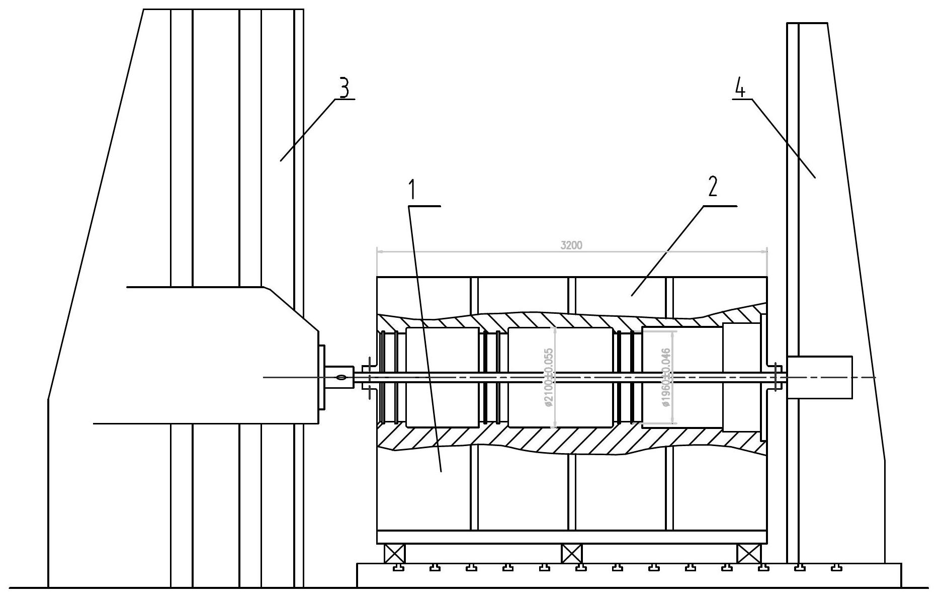
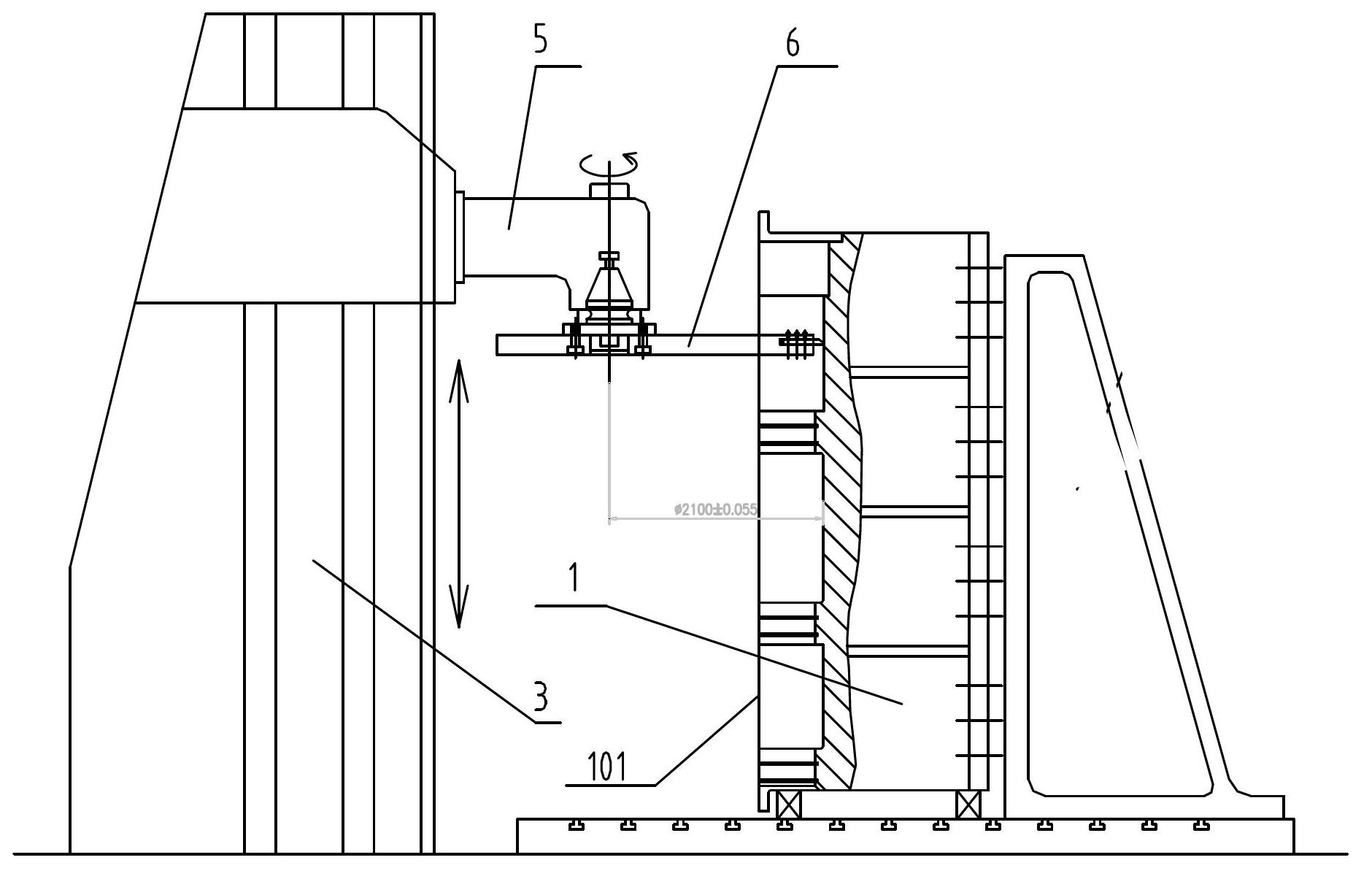
[0026] The processing method of this kind of large-scale box hole system proposed by the present invention breaks the thinking of the traditional processing technology, which is to carry out boring processing on the upper box body 2 and the lower box body 1 of the large-scale box body in the state of separately existing respectively , The clamping method during processing ensures that the centerline of the main shaft of the boring machine 3 and the axis of the hole system are perpendicular to each other, and the vertical milling head 5 is used to process the hole system. see figure 2 , the processing method specifically includes the following steps:

[0027] 1) First process the horizontal datum for clamping on the side of the upper box 2 or the lower box 1;

[0028] 2) Install the upper box 2 or the lower box 1 on the ground platform of the horizontal floor boring ...


PUM


Abstract

The invention discloses a machining method for a large box body hole series and a jig cutter box. The method performs boring on an upper box body and a lower box body of a large box body, which are independent from each other, the clamping mode during machining ensures that a center line of the main shaft of a boring machine is perpendicular to the axes of the hole series, and a vertical milling head is adopted for machining the hole series. The jig cutter box comprises a strip-shaped box body; an internal spline hole matched with the vertical milling head of the boring machine is formed at the tail of the box body; thread through holes are formed at the periphery of the internal spline hole; a notch structure used for clamping a milling cutter is arranged at the head of the box body; and a plurality of threaded holes and bolts matched with the threaded holes and used for fixing the milling cutter are formed on one side of the notch structure. The machining method breaks the existing machining thinking, adopts a box body split machining mode, can effectively guarantee the machining accuracy of the large box body hole series, and solves the problems of error of the linearity and the circularity of the hole series and the like caused by the drooping of a boring rod because of the deadweight in the prior art.

Description

technical field [0001] The invention belongs to the technical field of large-scale mechanical processing, and relates to a method for processing a hole system, in particular to a method for processing a large-scale box hole system and a tool box. Background technique [0002] In recent years, with the rapid development of domestic industrial science and technology, large-scale box products have appeared in metallurgy, power generation and other fields. The diameter of the hole system in the box is φ1950, the hole depth is 3500, the coaxiality of the hole system is required to be 0.05, and the roughness Ra The value is 3.2mm, and the precision requirement is high. [0003] The traditional processing method of the large box is carried out on a horizontal floor boring machine: after the joint surfaces of the upper and lower boxes are processed separately, the upper box 2 and the lower box 1 are assembled into a whole, and then the box is processed on a large boring machine. bo...

Claims


Application Information

Patent Timeline
Patent Type & Authority Applications(China)
IPC IPC(8): B23C3/00B23Q3/12
Inventor 韩铭金丁占军孟茂生段晓宾
Owner SINOSTEEL XIAN MACHINERY
Why Eureka
Try Eureka