Three-dimensional printing device, three-dimensional printing system and three-dimensional printing method
A technology of three-dimensional printing and printing department, which is applied to the printing, printing device and printing of special varieties of printed matter. It can solve the problems of image surface cracks, high cost, time-consuming three-dimensional printing, etc., and achieve high quality and low price. Effect
- Summary
- Abstract
- Description
- Claims
- Application Information
AI Technical Summary
Problems solved by technology
Method used
Image


Examples
Embodiment 1
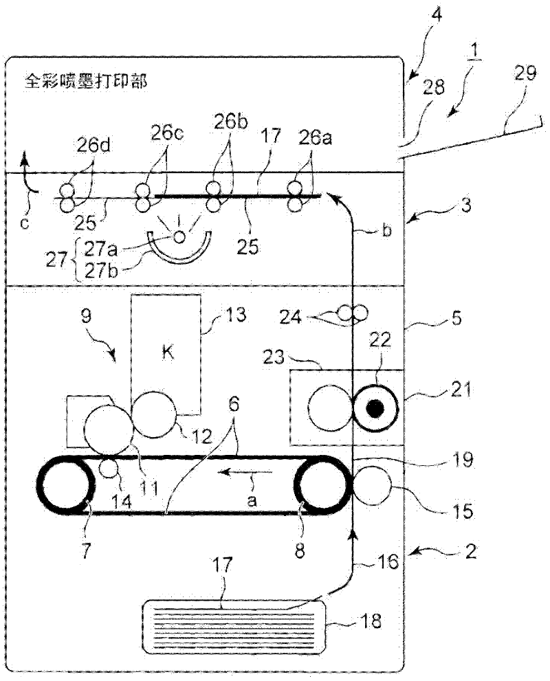
[0074] Figure 4A , Figure 4B and Figure 4C It is a schematic diagram of the basic concept of producing a three-dimensional surface on the thermally expandable sheet 17 in the first embodiment of the three-dimensional printing apparatus 1 having the above-mentioned structure. Figure 4A The structure of the thermally expandable sheet 17 used in Example 1 is shown. Figure 4B It is used to illustrate the processing principle of selectively foaming and partially bulging the heat-expandable sheet 17 . Figure 4C It is a cross-sectional view showing the machining result.
[0075] Such as Figure 4A As shown, the thermally expandable sheet 17 is composed of a base material 56 and a foamed resin layer 57 containing a thermal foaming agent coated on the base material 56 . The base material 56 is made of cloth such as paper or canvas, or panel materials such as plastic, and its material is not particularly limited. As the thermally expandable sheet 17 composed of the substrate...
Embodiment 2
[0098] Figure 6A ~ Figure 6C It is a diagram showing the basic principle of the processing of the second embodiment in the three-dimensional printing apparatus 1 . Figure 6A is a plan view of the thermally expandable sheet 17 with the foamed resin layer 57 facing upward, Figure 6B It is its A-A' section plane view. A solid black image 71 and a solid gray image 72 are printed on the surface of the foamed resin layer 57 by varying the density of black printing.
[0099] The pure black image 71 and the pure gray image 72 have different heat absorption rates due to differences in black density. Therefore, if the thermally expandable sheet 17 is subjected to heating and foaming treatment, as Figure 6C As shown, the portion L of the pure black image 71 of the foamed resin layer 57 is largely raised due to thermal expansion.
[0100] Furthermore, although the portion N of the pure gray image 72 rises due to thermal expansion, the amount of rise is smaller than that of the por...
PUM
 Abstract
Description
Claims
Application Information
 - Generate Ideas
- Intellectual Property
- Life Sciences
- Materials
- Tech Scout
- Unparalleled Data Quality
- Higher Quality Content
- 60% Fewer Hallucinations
Browse by: Latest US Patents, China's latest patents, Technical Efficacy Thesaurus, Application Domain, Technology Topic, Popular Technical Reports.
© 2025 PatSnap. All rights reserved.Legal|Privacy policy|Modern Slavery Act Transparency Statement|Sitemap|About US| Contact US: help@patsnap.com