
High-temperature-resistance abrasion-resistance nanometer bearing fan

A wear-resistant and high-temperature-resistant technology, applied in coatings, liquid fuel engines, mechanical equipment, etc., can solve problems such as increased noise, violent vibration of fans, and bearing wear, achieving strong high-temperature resistance, prolonging service life, non-volatile effect

Inactive Publication Date: 2012-08-29
SHENZHEN JINGUHONG HARDWARE TECH
View PDF6 Cites 4 Cited by
  • Summary
  • Abstract
  • Description
  • Claims
  • Application Information

AI Technical Summary

Problems solved by technology

Oil-impregnated bearings are sleeve bearings that use sliding friction. Lubricating oil is used as a lubricant and drag reducer. In the initial use, the operating noise is low and the manufacturing cost is also low. However, this kind of bearing wears seriously, and its service life is far behind that of ball bearings. Moreover, if this kind of bearing is used for a long time, due to the reason of the oil seal, the lubricating oil will gradually volatilize, and the dust will also enter the bearing, which will cause problems such as slow fan speed and increased noise. In serious cases, the fan will be eccentric due to bearing wear. Violent vibrations are caused, and these phenomena appear, either open the oil seal to refuel, or buy a new fan; the ball bearing has good operation stability, but the price is also high. The above-mentioned defects of the existing bearings limit the service life of the fan.

Method used


Image

  • High-temperature-resistance abrasion-resistance nanometer bearing fan
  • High-temperature-resistance abrasion-resistance nanometer bearing fan
  • High-temperature-resistance abrasion-resistance nanometer bearing fan

Examples


Embodiment Construction

[0019] The following is a further description of the high-temperature-resistant and wear-resistant nano-bearing fan described in the application of the present invention in conjunction with the accompanying drawings. On the basis of the same or similar principles, the improvement of the fan, including its shape, size, material used, and the increase, decrease or replacement of corresponding parts, in order to achieve basically the same technical effect, are all included in this Within the technical solution claimed in the invention application.

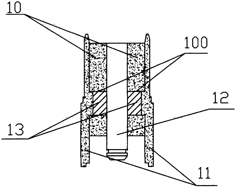
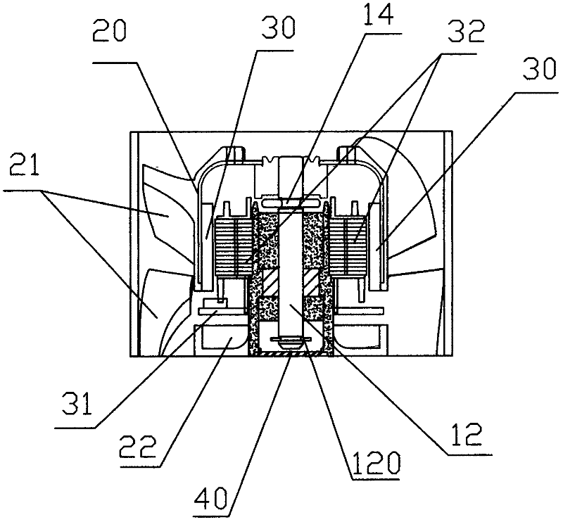
[0020] like figure 1 As shown, the high-temperature-resistant and wear-resistant nano-bearing fan described in the application of the present invention is a bearing made of nano-materials, including an outer ring 11 and an inner ring 10, wherein the inner ring 10 is a discontinuous upper and lower ring structure, the middle part is a housing cavity 100, the housing cavity 100 is provided with oil storage cotton 13, the rotating shaft...


PUM


Abstract

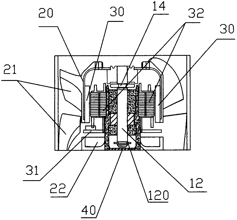
The invention provides a high-temperature-resistance abrasion-resistance nanometer bearing fan, which comprises a fan frame of a fan, wherein the fan frame of the fan is positioned at the bottom, a case is positioned at the upper part of the fan frame of the fan, a plurality of fan blades are in annular staggered distribution in a way of surrounding the case, an annular magnetic sheet is arranged in the case in a tight pasting way, multilayer silicon steel sheets are arranged in the magnetic sheet and are overlapped, coils are wound on the silicon steel sheets, the silicon steel sheets are annularly distributed in the magnetic sheet, in addition, nanometer bearings are placed in the centers of the silicon steel sheets, a motor rotating shaft is positioned in the nanometer bearings, a circuit board is connected with the coils wound on the silicon steel sheets, further, the nanometer bearings comprise outer rings and inner rings, the inner rings are in two discontinuous annular structures: an upper annular structure and a lower annular structure, the middle is an accommodating cavity, oil storage cotton is arranged in the accommodating cavity, and the outer rings and the inner rings are made of nanometer materials. The high-temperature-resistance abrasion-resistance nanometer bearing fan has the advantages that the high-temperature-resistance and abrasion-resistance capability is high, the service life is greatly prolonged, and wide application prospects are realized.

Description

technical field [0001] The application of the present invention relates to a fan, especially a nano-material bearing, which has the effects of high temperature resistance and wear resistance, and belongs to the technical field of fan equipment. Background technique [0002] Bearing is a component that fixes and reduces the friction coefficient of the load during the mechanical transmission process. When other parts move relative to each other on the shaft, it is used to reduce the friction coefficient during the power transmission process and keep the center of the shaft fixed. , are widely used in mechanical equipment. [0003] Most of the existing bearing materials are steel, including bearing steel, carbon steel and stainless steel. Although steel bearings have the characteristics of good toughness, strong impact resistance and large bearing capacity, they are not resistant to wear and are easily damaged. Oxidation corrosion, not resistant to high temperature. There are...

Claims


Application Information

Patent Timeline
Patent Type & Authority Applications(China)
IPC IPC(8): F04D29/056
CPCF04D25/062F04D29/023F04D29/0566F05D2300/608F05D2300/611F05D2300/20F04D25/0606F04D29/056F04D29/083
Inventor 夏先其
Owner SHENZHEN JINGUHONG HARDWARE TECH
Learn More