Material taking device of high temperature reaction furnace

A reclaiming device, high temperature reaction technology, applied in furnaces, furnace components, lighting and heating equipment, etc., can solve problems such as dumping

Inactive Publication Date: 2012-08-29
SOLAR ENERGY&MATERIALS IN
View PDF5 Cites 3 Cited by
  • Summary
  • Abstract
  • Description
  • Claims
  • Application Information

AI Technical Summary

Problems solved by technology

[0013] The object of the present invention is to provide a high-temperature reaction furnace material reclaiming device, which can realize the connection of flow guide channels at the bottom or side wal...

Method used


Image

  • Material taking device of high temperature reaction furnace
  • Material taking device of high temperature reaction furnace
  • Material taking device of high temperature reaction furnace

Examples


Embodiment 1

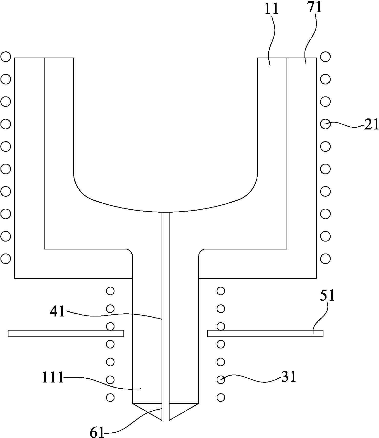
[0044] Such as figure 2 As shown, the reaction furnace in this embodiment 1 is a smelting crucible 11, and a thermal insulation layer 71 is provided outside it; a main furnace induction coil 21 is arranged outside the thermal insulation layer 71; The thermal switch induction coil 31 and the cooling air pipe 51 are provided; in this way, the induction heating of the reaction furnace and the flow guiding channel 41 is realized.

[0045] When working, the upper melting crucible 11 is heated and melted by the induction coil 21 of the main furnace to melt the reaction substance. At this time, the induction coil 31 of the thermal switch is in the non-working state, and the reactant melt flows into the guide channel 41 under the action of gravity, and the melt in the flow When the temperature drops, it condenses into a solid, blocks the guide channel 41, and achieves the effect of turning off the thermal switch. When the reactant melt needs to be discharged, the thermal switch indu...

Embodiment 2

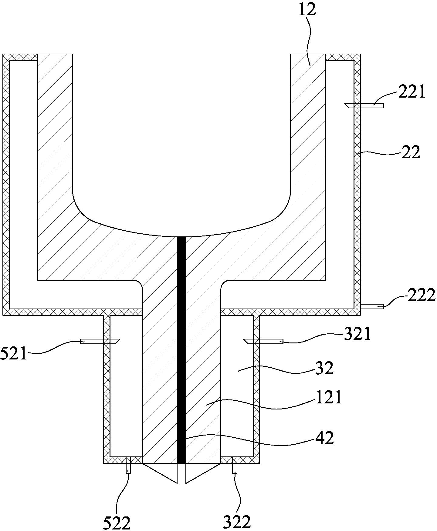
[0047] Such as image 3 As shown, the reaction furnace in this embodiment 2 is a smelting crucible 12, and a main furnace heating cylinder 22 is provided outside it, and the main furnace heating cylinder 22 is a closed cylinder, on which a main furnace heating The oil inlet 221 and the hot oil outlet 222 of the main furnace; and the outside of the guide seat 121 is provided with a thermal switch heating cylinder 32, and the heating cylinder 32 is a closed cylinder, and the cylinder is provided with a thermal switch for heating equipment. The inlet 321 and the hot oil outlet 322 are also provided with a cooling substance inlet 521 and a cooling substance outlet 522 on the missing body. In this way, heat conduction heating to the reaction furnace and the flow guiding channel 42 is realized.

[0048] During operation, the upper melting crucible 12 is heated and melted by injecting hot oil into the main furnace heating cylinder 32 to heat and melt the reaction substance. The reac...

Embodiment 3

[0050] Such as Figure 4As shown, the reaction furnace in this embodiment 3 is a smelting crucible 13, and a main furnace resistance heater 23 is provided outside it; a main furnace heat insulation layer 73 is set outside the main furnace resistance heater 23; The outside of the seat 131 is provided with a thermal switch resistance heater 33 , and a thermal switch heat insulation layer 83 is provided outside the thermal switch resistance heater 33 .

[0051] When working, the upper melting crucible 13 is heated and melted by the main furnace resistance heater 23 to melt the reaction substance. At this time, the thermal switch resistance heater 33 is in the non-working state, and the cooling pipe 53 injects the cooling substance, and the reactant melt flows into the flow guide under the action of gravity Channel 43, the temperature of the melt decreases during the flow and condenses into a solid, blocking the guide channel 43 to achieve the effect of turning off the thermal swi...


PUM


Abstract

The invention discloses a material taking device of a high temperature reaction furnace. Main furnace heating equipment is arranged on the outer edge of a furnace body, wherein a flow guide channel is arranged at the lower part of the furnace body; a pouring nozzle is arranged at the outer end of the flow guide channel; the flow guide channel is arranged in a flow guide seat connected with the furnace body; and a thermal switch system for controlling the temperature of the flow guide seat is arranged at the outer part of the flow guide seat. Reactive substances in the flow guide channel are solidified or melted through temperature control changes conducted by the thermal switch system, so that the flow guide channel is closed or connected, normal reaction operation of the reaction furnace is realized and reactants can be taken out. The reactive substances are only contacted with the external environment at a distance from the pouring nozzle to a die or a container, so that oxidation reaction of the reactive substances is controlled; as the flow is guided below a liquid level, the phenomenon of slag inclusion can be completely avoided from occurring to floating reactants, so that fresh gas cannot be wrapped into the floating reactants to form more air holes and air bubbles; and the flow guide channel can be rapidly opened and closed under the temperature control, so that the metering of pouring can be well controlled and the aim of accurate pouring is achieved.

Description

technical field [0001] The invention relates to the field of auxiliary equipment for smelting reaction furnaces, in particular to a material reclaiming device for high-temperature reaction furnaces. Background technique [0002] In the process of using a reaction furnace for heating operation, part or all of the reaction substances in the reaction furnace often need to be taken out during the reaction or after the reaction. [0003] There are several ways to take it out: [0004] 1. The opening on the bottom or side wall of the reaction furnace is connected to the guide channel, and the switch valve is set on the guide channel to control the outflow time and the outflow quantity. [0005] 2. Let the reaction furnace tilt to pour out the reaction substance. [0006] 3. Using a pump, let the feed pipe of the pump be inserted into the reaction substance to extract. [0007] The above methods can be used in the medium and low temperature field, but in the traditional process ...

Claims


Application Information

Patent Timeline
IPC IPC(8): F27D3/15
Inventor 刘荣隆石磊
Owner SOLAR ENERGY&MATERIALS IN
Why Eureka
Try Eureka