Signal processing circuit, physical quantity detecting device, and angular speed detecting device

一种信号处理电路、信号的技术,应用在测量装置、陀螺效应进行速度测量、速度/加速度/冲击测量等方向,能够解决电路面积增加、叠加、有悖小型化等问题,达到降低折返噪声、低噪声、抑制电路面积的增加的效果

Active Publication Date: 2012-08-29
SEIKO EPSON CORP +1
View PDF8 Cites 24 Cited by
  • Summary
  • Abstract
  • Description
  • Claims
  • Application Information

AI Technical Summary

Problems solved by technology

[0007] However, due to the sampling of the SCF, f d 、2f d 、3f d , ... and other frequency bands will fold back to the DC band, so the noise in these frequency bands will be superimposed on the detection signal
In the past, the noise generated in the SCF was relatively small and could be ignored. However, when it is desired to achieve lower noise, the noise generated in the SCF cannot be ignored.
By increasing the sampling frequency of the SCF, the amount of noise folded back to the DC band can be reduced. However, since there is generally no signal with a frequency higher than the drive frequency of the vibrator in the signal processing circuit, it is necessary to add a new signal with a frequency higher than the drive frequency. signal circuit
By adding a multiplier circuit such as a PLL (Phase Locked Loop: Phase Locked Loop circuit), although it is possible to generate a signal with a multiplied frequency of the driving frequency, the circuit area is greatly increased, which is contrary to the demand for miniaturization.

Method used


Image

  • Signal processing circuit, physical quantity detecting device, and angular speed detecting device
  • Signal processing circuit, physical quantity detecting device, and angular speed detecting device
  • Signal processing circuit, physical quantity detecting device, and angular speed detecting device

Examples


Embodiment Construction

[0034]Preferred embodiments of the present invention will be described in detail below using the drawings. Furthermore, the embodiments described below are not intended to unduly limit the content of the present invention described in the claims. In addition, not all the configurations described below are essential configuration requirements of the present invention.

[0035] 1. Physical quantity detection device

[0036] A physical quantity detecting device (angular velocity detecting device) that detects an angular velocity as a physical quantity will be exemplified below. The present invention is applicable to a device capable of detecting any one of various physical quantities such as angular velocity, angular acceleration, acceleration, and force.

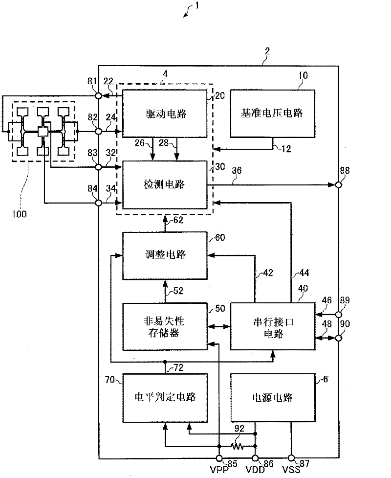
[0037] figure 1 It is a functional block diagram of an angular velocity detection device (an example of a physical quantity detection device) of this embodiment. The angular velocity detection device 1 of the present embod...


PUM


Abstract

The invention provides a signal processing circuit, a physical quantity detecting device, an angular speed detecting device, an integrated circuit device and an electronic device. The increasing of circuit area can be prevented and less noise can be realized. An I / V switching circuit (a current / voltage switching part) converts the oscillation current of an oscillator into voltage. A RC filter (a phase displacement part) conducts a phase displacement on the output signal of the I / V switching circuit. A full-wave rectification circuit (a part of a drive amplitude control part) conducts binaryzation on the signal undergoing the phase displacement, forming a switching control signal. A comparing machine (a reference signal generating part) generates a reference signal for synchronous detection based on the output signal of the I / V switching circuit. An or circuit (a clock signal generating part) generates the clock signal for a switch capacitance filter whose frequency is two times as that of a drive signal, based on the phase difference between the reference signal and the switching control signal.

Description

technical field [0001] The present invention relates to a signal processing circuit, a physical quantity detection device, an angular velocity detection device, an integrated circuit device and electronic equipment. Background technique [0002] Gyro sensors are installed in various electronic devices such as digital cameras, navigation devices, and mobile phones. Based on the magnitude of the angular velocity detected by the gyro sensor, processing such as shake correction, dead reckoning, and interactive sensing is performed. [0003] In recent years, miniaturization and high detection accuracy of gyro sensors are required, and as gyro sensors satisfying these requirements, for example, vibrating gyro sensors using the resonance phenomenon of quartz resonators are widely used. In the case of using such a vibrating gyro sensor, since the detection signal output from the vibrator becomes smaller due to miniaturization, in order to achieve high detection accuracy, the signal ...

Claims


Application Information

Patent Timeline
Patent Type & Authority Applications(China)
IPC IPC(8): G01C19/5776
CPCG01C19/5649G01C19/56G01C19/5614G01C19/5776
Inventor 柳泽良直押尾政宏菊池尊行西田稔洋高桥正行
Owner SEIKO EPSON CORP
Why Eureka
Try Eureka