Electromagnetic chuck control circuit

An electromagnetic chuck and control circuit technology, applied in the direction of electromagnets, electromagnets with armatures, etc., can solve the problems of complex circuits, difficult control and maintenance, etc.

Active Publication Date: 2014-10-29
云南省曲靖双友钢铁有限公司
View PDF4 Cites 0 Cited by
  • Summary
  • Abstract
  • Description
  • Claims
  • Application Information

AI Technical Summary

Problems solved by technology

[0004] The purpose of the present invention is to provide a control circuit for an electromagnetic chuck, which simplifies the circuit and makes the control and maintenance easy

Method used


Image

  • Electromagnetic chuck control circuit
  • Electromagnetic chuck control circuit
  • Electromagnetic chuck control circuit

Examples


Embodiment Construction

[0010] The technical solution will be further described as an embodiment below in conjunction with the accompanying drawings.

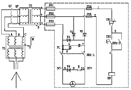
[0011] Referring to Figure 1, the electromagnetic chuck control circuit is mainly used in the circuit using the isolation transformer T2 between the electromagnetic chuck circuit and the system transformer T1. The isolation transformer T2 and the system transformer T1 are grounded E, the neutral line of the system transformer T1 is N, and 3 secondary The coils are A, B, and C, and the 3 secondary coils of the isolation transformer T3 correspond to a, b, and c. Specifically, the system transformer T1 and the isolation transformer T2 have an isolation switch QS and a circuit breaker QF indirectly; the secondary coil connectors a, b, and c of the isolation transformer T2 are respectively connected with fuses FU1, FU2, FU3, and fuses FU3, FU2, FU1 is respectively connected with the rectification circuit composed of rectification diodes V1, V2 and V3; the ...


PUM


Abstract

The invention relates to a control circuit of an electromagnetic chuck. The control circuit consists of a main loop and a control loop and is characterized in that the main loop is formed in the way that a rectifying circuit consisting of rectifying diodes V1, V2 and V3 is correspondingly connected onto fuses FU1, FU2 and FU3 led out from a secondary electrode of an isolation transformer T2, and the output ends of the rectifying diodes V1 to V3 are connected in parallel and are then connected with two ends of an electromagnetic chuck coil L through a main contact point KM1-1 of an alternating current contactor; and the control loop leads out two branch circuits from the positive ends of the rectifying diodes V2 and V3 and the connecting points of the fuses FU1 and FU2, and the two branch circuits are respectively connected with fuses FU4 and FU5, wherein the branch circuit of the fuse FU5 is connected with an auxiliary contact point KM1-2 of the alternating current contactor, then, a starting press button SB2 is connected in series, the branch circuit of the fuse FU4 is connected with a stop press button SB1, and two contact points of the SB1 and the SB2 are connected. The circuit is simplified, the maintenance cost is reduced, and the operation is simple; and the device intuition is high, the electric faults are reduced, the overhauling time is shortened, and the work efficiency of the electromagnetic chuck L is improved.

Description

technical field [0001] The invention relates to a control circuit of an electromagnetic chuck. Background technique [0002] Electromagnetic chucks are widely used in the production field. The control circuit of the original electromagnetic chuck is relatively complicated. Once a fault occurs, it will delay maintenance personnel a lot of time to find the fault. Maintenance is inconvenient. The DC contactor used has many faults and a large amount of maintenance. Because of the occurrence of electrical faults: a control line, a connection point, a component, a pair of contacts, etc. are all faults, any fault can make the electrical equipment unable to work, causing impact and loss to the normal operation of production , as users and maintenance personnel do not want this to happen frequently. [0003] There are many electrical components and control contacts in the main circuit and control circuit, especially when three bridge rectifier circuits are used. When each diode of a...

Claims


Application Information

Patent Timeline
Patent Type & Authority Patents(China)
IPC IPC(8): H01F7/18
Inventor 王世立
Owner 云南省曲靖双友钢铁有限公司
Why Eureka
Try Eureka