
Method for recovering energy when compressing a gas with a compressor

A technology for compressing gases and compressors, applied in the components of pumping devices for elastic fluids, mechanical equipment, machines/engines, etc. Sufficient, reduced calcification risk effect

Active Publication Date: 2012-08-29
ATLAS COPCO AIRPOWER NV
View PDF9 Cites 7 Cited by
  • Summary
  • Abstract
  • Description
  • Claims
  • Application Information

AI Technical Summary

Problems solved by technology

[0010] The disadvantage of this throttling is that the speed of the coolant passing through the heat exchanger is greatly reduced, which leads to calcification in the various heat exchangers
[0011] Another disadvantage: Limiting the velocity of the coolant in the different heat exchangers is not conducive to optimal heat transfer in said heat exchangers

Method used


Image

  • Method for recovering energy when compressing a gas with a compressor
  • Method for recovering energy when compressing a gas with a compressor
  • Method for recovering energy when compressing a gas with a compressor

Examples


Embodiment Construction

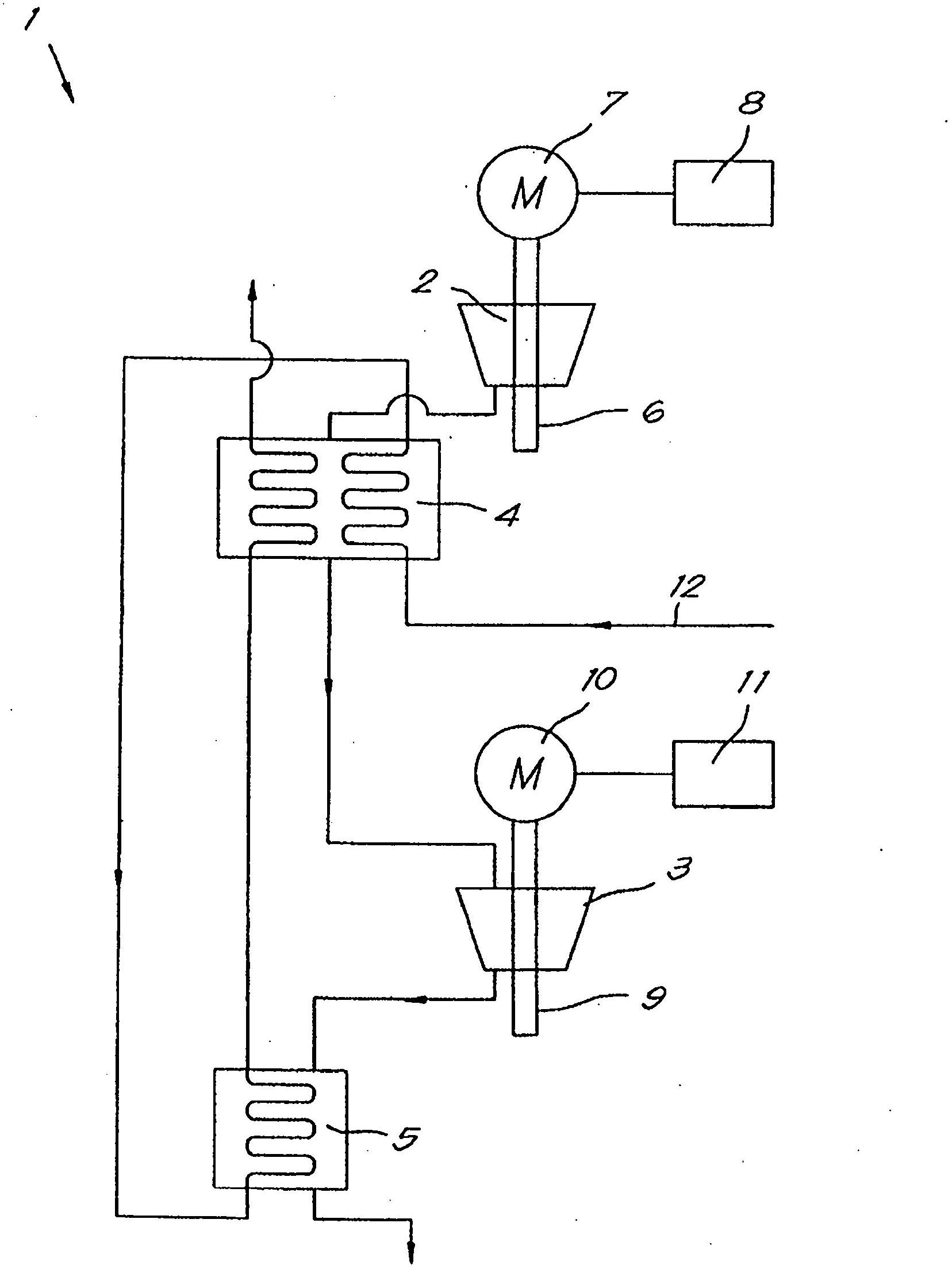
[0037] figure 1 A compressor 1 for compressing a gas such as air is shown, in this case having two compression stages connected in series. Each compression stage is realized by a turbo compressor head, that is, a low-pressure compressor head 2 and a high-pressure compressor head 3 respectively.

[0038] In this particular example, the outlet temperature of the first low-pressure compressor block 2 is higher than the outlet temperature of the second high-pressure compressor block 3 .

[0039] In this case, heat exchangers are arranged downstream of each compressor head 2 and 3, specifically, the first heat exchanger 4 or intercooler is arranged downstream of the low-pressure compressor head 2, and the second heat exchanger The cooler 5 or aftercooler is arranged downstream of the high pressure compressor head 3 .

[0040] The low-pressure compressor head 2 is connected to a first shaft 6 driven by a first motor 7 equipped with a motor control 8 .

[0041] The high-pressure c...


PUM


Abstract

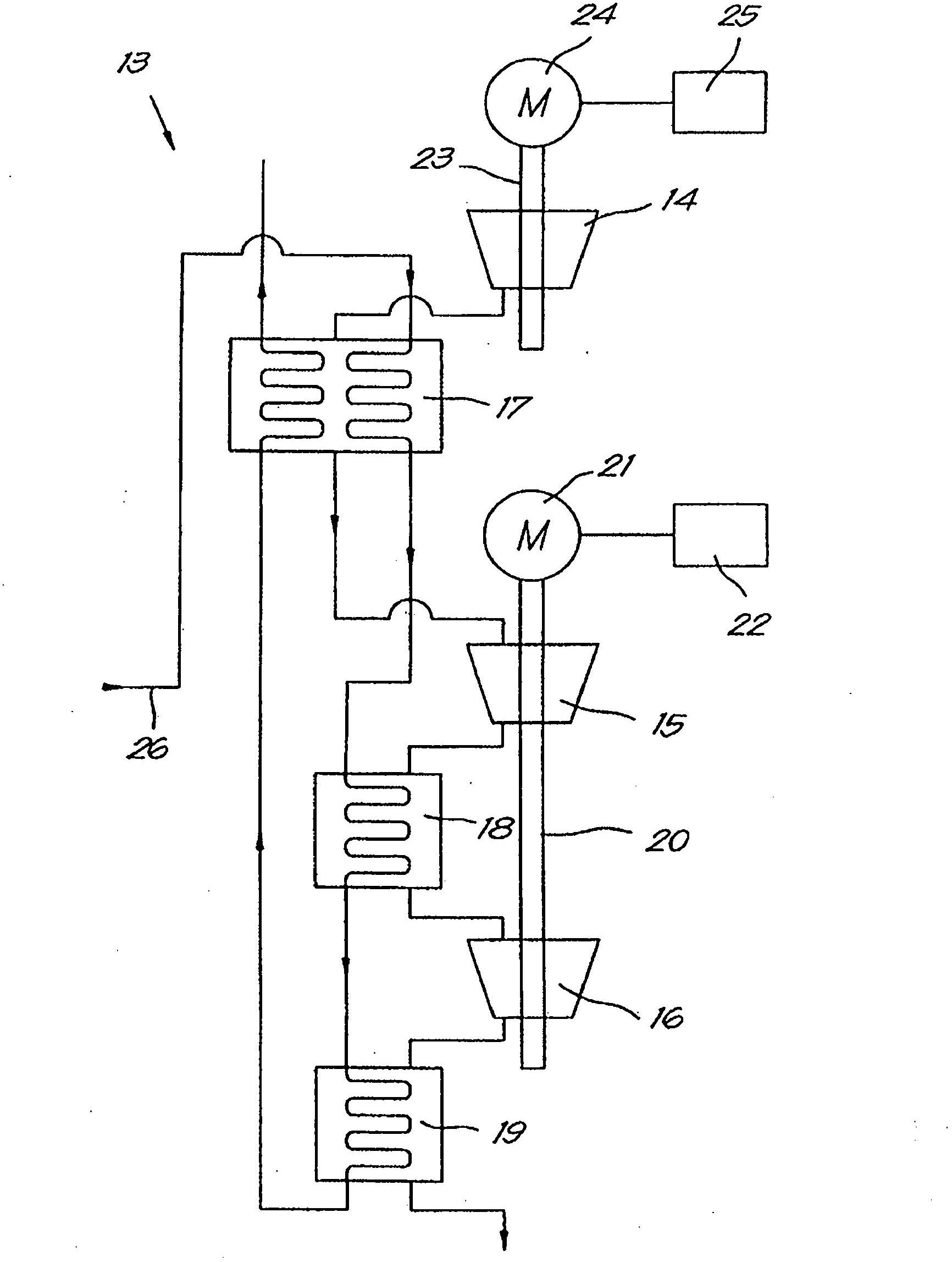
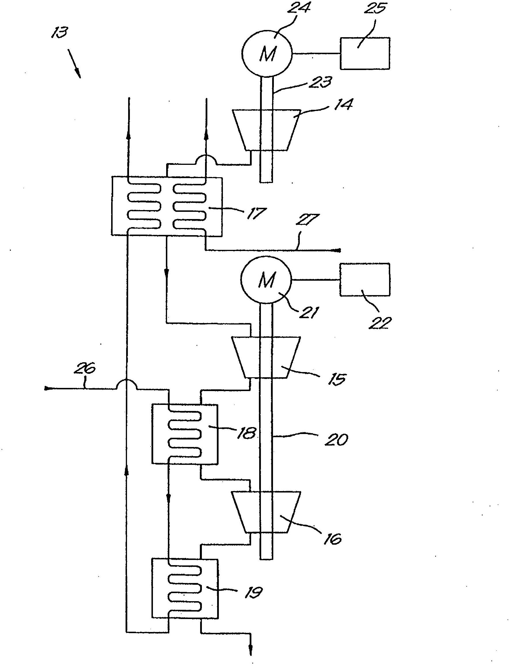
Method for recovering energy when compressing a gas with a compressor (1) with two or more compression stages, with each stage realised by a compressor element (2,3), whereby in each case downstream from at least two aforementioned compressor elements there is a heat exchanger (4,5) with a primary and a secondary part, whereby the coolant is guided successively in series through the secondary part of at least two heat exchangers (4,5), whereby the sequence in which the coolant is guided through the heat exchangers (4,5) is chosen such that the temperature at the inlet of the primary part of at least one subsequent heat exchanger is higher than or equal to the temperature at the inlet of the primary part of a preceding heat exchanger, as seen in the direction of flow of the coolant, and whereby at least one heat exchanger (4 and / or 17) is provided with a tertiary part for a coolant.

Description

technical field [0001] The invention relates to a method for recovering energy. [0002] In particular, the invention relates to a method of recovering energy when compressing a gas by a compressor having two or more stages of compression, each stage being implemented by a compressor block. In each case, downstream of at least two of the aforementioned compressor heads there is a heat exchanger having a primary side and a secondary side, in particular through which compressed gas from a compression stage upstream of the heat exchanger is led the primary side of the heat exchanger, while the coolant is directed through the secondary side to recover part of the heat of compression of the compressed gas. Background technique [0003] It is well known that the gas temperature at the inlet of the compression stage has a significant impact on the energy consumption of the compressor. [0004] It is thus necessary to cool the gas between successive stages of compression. [0005...

Claims


Application Information

Patent Timeline
Patent Type & Authority Applications(China)
IPC IPC(8): F04B39/06F04C29/04F04D29/58F28D21/00F24J3/00
CPCF04B39/06F04C29/04F28D21/0001F04D29/5833F25J2205/04F25J2230/04F25J3/04018F04D29/58F28D21/00
Inventor S·J·R·J·扬森斯
Owner ATLAS COPCO AIRPOWER NV
Learn More