
Roller servo storage system

A roller and material storage technology, applied in the field of roller servo material storage system, can solve the problem of high cost of planetary gear transmission device and cycloidal gear transmission device

Inactive Publication Date: 2012-09-05
MODAOWN & SOMAX INDUSRY INC
View PDF8 Cites 3 Cited by
  • Summary
  • Abstract
  • Description
  • Claims
  • Application Information

AI Technical Summary

Problems solved by technology

[0012] Another object of the present invention is to provide a roller servo storage system, which can effectively improve the problem of high cost of the conventional planetary gear transmission device and cycloidal gear transmission device, and can further improve the conversion efficiency of the transmission device, so that The speed change device is more suitable for the roller servo storage system

Method used

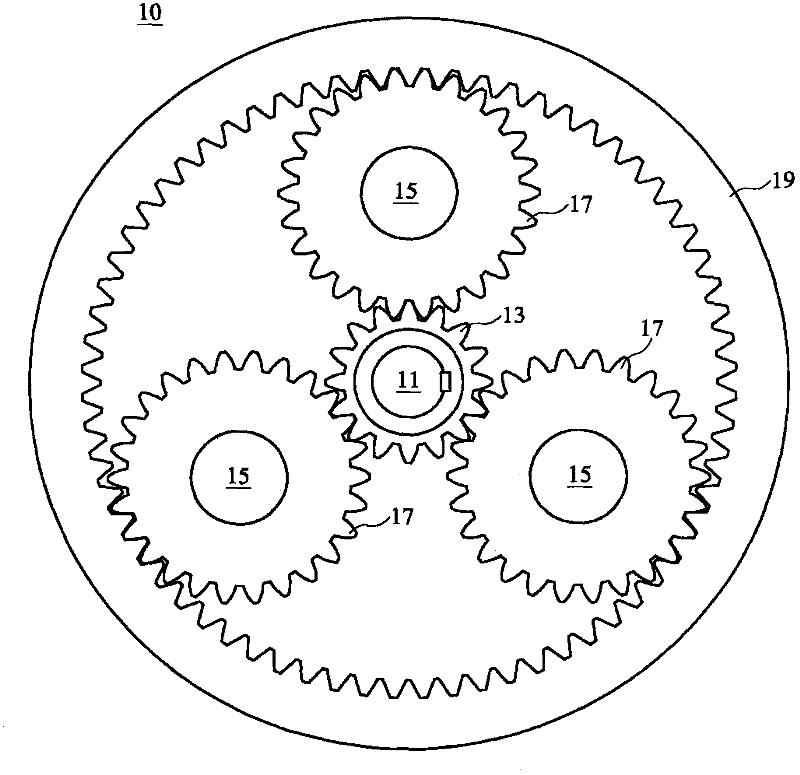
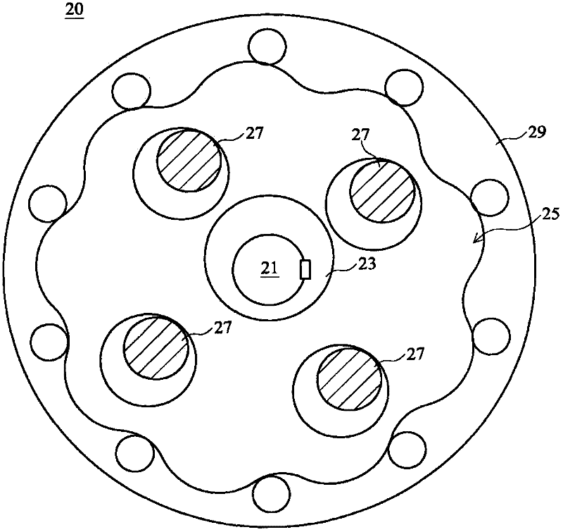

Image

  • Roller servo storage system
  • Roller servo storage system
  • Roller servo storage system

Examples


Embodiment Construction

[0056] The connection mentioned in the present invention refers to a direct connection or an indirect connection between one or more objects or components, for example, there may be one or more intermediate connections between one or more objects or components.

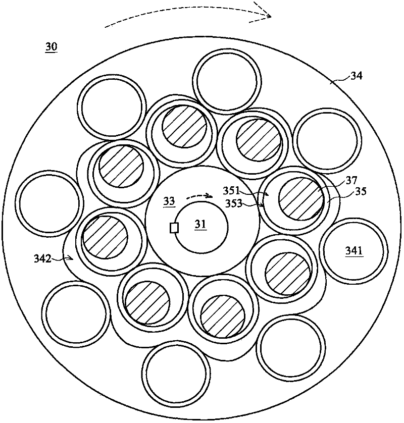
[0057] see image 3 and Figure 4 Shown are the front side schematic diagram and the rear side schematic diagram of an embodiment of the transmission device of the roller servo storage system of the present invention, respectively. As shown in the figure, the speed change device 30 of the present invention includes an input shaft 31, an eccentric wheel 33, a plurality of hollow cylinders 35, a plurality of pins 37 and an output disk 39, wherein a plurality of hollow cylinders 35 are arranged around Around the eccentric wheel 33, a rolling gear structure is formed.

[0058] In the embodiment of the present invention, one end of the input shaft 31 can be connected with an external motor, and transmit the power generat...


PUM


Abstract

The invention discloses a roller servo storage system. The system mainly comprises an input shaft, an eccentric wheel, a bearing, a plurality of hollow column bodies, a plurality of bolts, an output disc, a servo motor and an injection molding device, wherein the servo motor is used for driving the input shaft to rotate; the input shaft is about to drive the eccentric wheel to swing when rotating, so that the eccentric wheel pushes the hollow column bodies via the bearing and the driven hollow column bodies drive the output disc to rotate via the bolts and drive the injection molding device; and the bearing is arranged on the eccentric wheel, so that the eccentric wheel is about to rotate relative to the bearing in the process of pushing the hollow column bodies, thus wear generated by the eccentric wheel and the hollow column bodies in the operation processes can be reduced and the service life and efficiency of the roller servo storage system can be improved.

Description

technical field [0001] The invention relates to a roller servo storage system, which can reduce the wear of the eccentric wheel and the hollow cylinder during operation, and improve the service life and performance of the roller servo storage system. Background technique [0002] The transmission device is a power transmission mechanism that is often used in industrial machinery. It mainly uses the combination of multiple gears to achieve the purpose of changing the speed of the motor (motor). Generally speaking, the transmission device can be used to convert the high-speed, low-torque mechanical power generated by the power source (internal combustion engine or electric motor) into more effective low-speed and high-torque power, thereby driving the mechanical device. Special gears may also be used to increase speed and reduce torque. [0003] Among the mechanisms currently used to transmit power and motion, transmissions are used in a wide range of applications. It can be...

Claims


Application Information

Patent Timeline
IPC IPC(8): B29C45/17F16H1/28
Inventor 周燕忠
Owner MODAOWN & SOMAX INDUSRY INC
Learn More