

Roll angle measurement device and method based on array-type multiple reflections
A technology of roll angle measurement and multiple reflections, applied in the direction of measuring devices, optical devices, instruments, etc., can solve problems such as difficult resolution, and achieve the effect of improving resolution
- Summary
- Abstract
- Description
- Claims
- Application Information
AI Technical Summary
Problems solved by technology
Method used
Image


Examples
Embodiment Construction
[0019] The present invention is described in further detail below in conjunction with accompanying drawing:
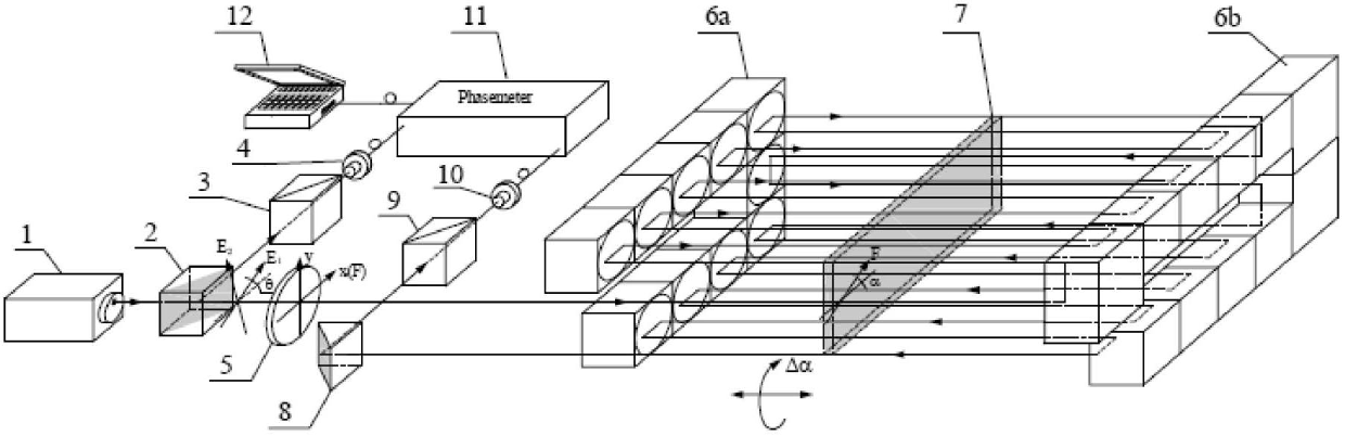
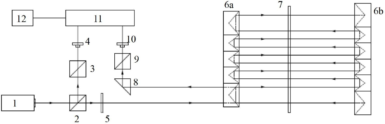
[0020] see figure 1 with figure 2 , the present invention is based on the rolling angle measuring device of array type multiple reflection, comprises dual-frequency laser 1, 1 / 2 wave plate 7 and two sets of corner cube arrays; After the optical axis of dual-frequency laser 1, beam splitting prism 2 is arranged, A first analyzer 3 and a first photoelectric receiver 4 are provided on the reflected optical axis of the beam splitting prism 2; a 1 / 4 wave plate 5 is provided on the transmitted optical axis of the beam splitting prism 2; 1 / 2 wave plate 7 is located in two sets of In the middle of the corner cube array; on the outgoing optical axis of the two sets of corner cube arrays, a right-angle reflective prism 8 is arranged, and on the reflected optical axis of the right-angle reflector 8, a second analyzer 9 and a second photoelectric receiver 10 are arranged ; The ...
PUM
 Abstract
Description
Claims
Application Information