Supercharge Your Innovation With Domain-Expert AI Agents!

Differential radio frequency switch circuit

A technology of radio frequency switches and circuits, applied in the direction of electronic switches, electrical components, pulse technology, etc., can solve problems such as complex methods, and achieve the effect of convenient design

Active Publication Date: 2015-06-03
江苏钜芯集成电路技术股份有限公司
View PDF2 Cites 0 Cited by
  • Summary
  • Abstract
  • Description
  • Claims
  • Application Information

AI Technical Summary

Problems solved by technology

Although the switching circuit can improve the input / output power characteristics on the basis of the conventional RF switching circuit, its circuit loss is still above 0.5dB
[0004] In addition, there is a parallel distributed field effect transistor method, which is more complicated and requires special design of semiconductor switching devices

Method used


Image

  • Differential radio frequency switch circuit
  • Differential radio frequency switch circuit

Examples


Embodiment 1

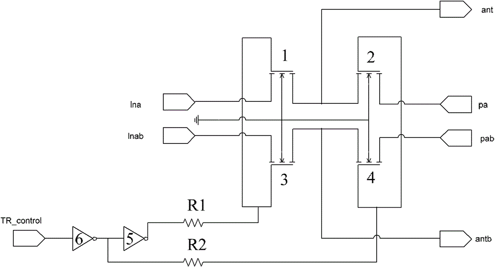
[0017] This embodiment provides a differential radio frequency switch circuit integrated on the chip, such as figure 2 As shown, the differential RF switch circuit is mainly composed of four NMOS transistors, which are the first NMOS transistor 1, the second NMOS transistor 2, the third NMOS transistor 3, and the fourth NMOS transistor 4; wherein, the first NMOS transistor 1 The drain of the second NMOS transistor 2 is connected to the source, the drain of the third NMOS transistor 3 is connected to the source of the fourth NMOS transistor 4; the gate of the first NMOS transistor 1 is connected to the gate of the third NMOS transistor 3 The gate of the second NMOS transistor 2 is connected to the gate of the fourth NMOS transistor 4; the pinch-off point of the first NMOS transistor 1, the pinch-off point of the second NMOS transistor 2, and the pinch-off point of the third NMOS transistor 3 and the pinch-off points of the fourth NMOS transistor 4 are grounded; the source of t...


PUM


Abstract

The invention discloses a differential radio frequency switch circuit which comprises a first NMOS (N-channel Mental-oxide-semiconductor) pipe, a second NMOS pipe, a third NMOS pipe and a fourth NMOS pipe, wherein a drain electrode of the first NMOS pipe is connected with a source electrode of a second NMOS pipe, and a drain electrode of the third NMOS pipe is connected with a source electrode of the fourth NMOS pipe; a grid electrode of the first NMOS pipe is connected with a grid electrode of the third NMOS pipe, and a grid electrode of the second NMOS pipe is connected with a grid electrode of the fourth NMOS pipe; a pinch-off point of the first NMOS pipe, a pinch-off point of the second NMOS pipe, a pinch-off point of the third NMOS pipe and a pinch-off point of the fourth NMOS pipe are all connected with the ground; a source electrode of the first NMOS pipe is connected with an LNA (low-noise amplifier) interface, and a drain electrode of the second NMOS pipe is connected with a PA (power amplifier) interface; and the grid electrode the first NMOS pipe and the grid electrode of the third NMOS pipe are connected with a resistor R1, and the grid electrode of the second NMOS pipe and the grid electrode of the fourth NMOS pipe are connected with a resistor R2. The differential radio frequency switch circuit provided by the invention adopts a full NMOS design, a gate is connected in series with the resistors, the influence of capacitance on each MOS pipe on a radio-frequency signal can be effectively reduced, meanwhile, the series resistors isolates noises, and the integral radio frequency loss of the circuit is within 0.5dB.

Description

technical field [0001] The invention belongs to the technical field of electronic circuits and relates to a differential radio frequency switch circuit. Background technique [0002] In a wireless or mobile communication system, a radio frequency switch (RF switch) is often used to select a radio frequency channel. For example, radio frequency switches are used to select the receiving and transmitting channels, so as to realize the reception and transmission of wireless signals under the condition of sharing the antenna; in order to increase the anti-jamming performance in military broadband radio stations, radio frequency switches are used to select filters of different frequency bands. In these systems, RF switches are generally required to have as low a drop loss and high isolation as possible. Due to the non-ideality of the switching device, the RF switching circuit has a certain insertion loss and the isolation is limited. It is difficult to achieve high isolation cha...

Claims


Application Information

Patent Timeline
Patent Type & Authority Patents(China)
IPC IPC(8): H03K17/56
Inventor 文耀锋
Owner 江苏钜芯集成电路技术股份有限公司
Features
  • R&D
  • Intellectual Property
  • Life Sciences
  • Materials
  • Tech Scout
  • Unparalleled Data Quality
  • Higher Quality Content
  • 60% Fewer Hallucinations
Learn More