Electric kettle

An electric kettle and kettle technology, which are applied to water boiling appliances, temperature control without auxiliary power supply, and applications, can solve the problems of inconvenient cleaning, repeated heating, and affect the appearance, and achieve simple structure, excellent performance, and simple assembly. Effect

Active Publication Date: 2012-09-12
ZHEJIANG SHAOXING SUPOR DOMESTIC ELECTRICAL APPLIANCE CO LTD
View PDF7 Cites 13 Cited by
  • Summary
  • Abstract
  • Description
  • Claims
  • Application Information

AI Technical Summary

Problems solved by technology

[0002] Consumers are very familiar with electric kettles, and technicians in the field of electric kettle industry are also very familiar with the structure of electric kettles. Most ordinary electric kettles control the power off of electric kettles through the steam generated after boiling water in electric kettles. The use of steam to control the power off of the electric kettle is defective; the first defect is that the steam generated by the electric kettle equipped with a steam conduit enters the steam conduit after the boiling water is boiled, and the steam in the steam pipe will form condensed water after cooling, and the Condensed water will flow to the electric control part at the bottom. Such a structure is actually a safety hazard. The second defect is that at a higher altitude, even if the water boils, it will not reach the set boiling temperature because there is no sufficient heat generated. If there is a large amount of steam, the heating power supply continues to heat, and the power supply cannot be cut off immediately, which has hidden dangers of safety accidents; the third defect is that the steam conduit is placed in the kettle, or the steam switch is placed on the handle of the electric kettle. These structures are not conducive to cleaning, and they cannot be placed. It is washed directly in water and this structure affects the appearance
The above-mentioned technical solutions, or there are technical defects that cannot be waterproofed, inconvenient to clean, or there is a situation of repeated heating, which needs to be improved

Method used


Image

  • Electric kettle
  • Electric kettle
  • Electric kettle

Examples


Embodiment Construction

[0025] The present invention will be further described below in conjunction with specific examples, but the present invention is not limited to these specific implementations. Those skilled in the art will realize that the present invention covers all alternatives, modifications and equivalents as may be included within the scope of the claims.

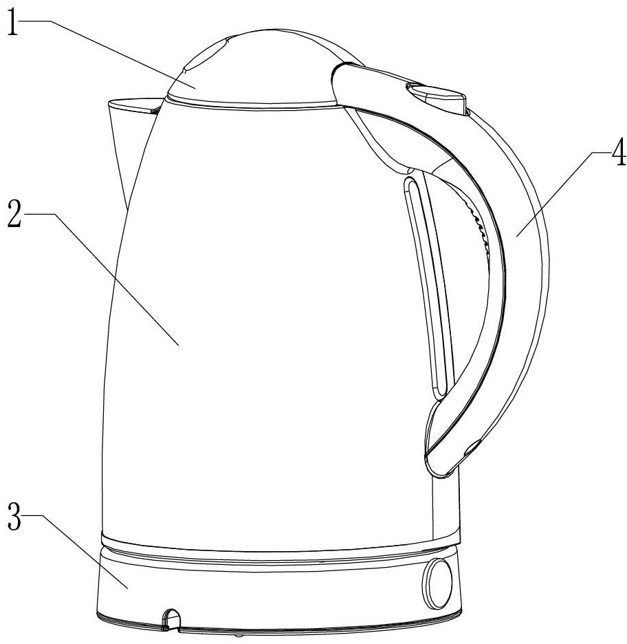
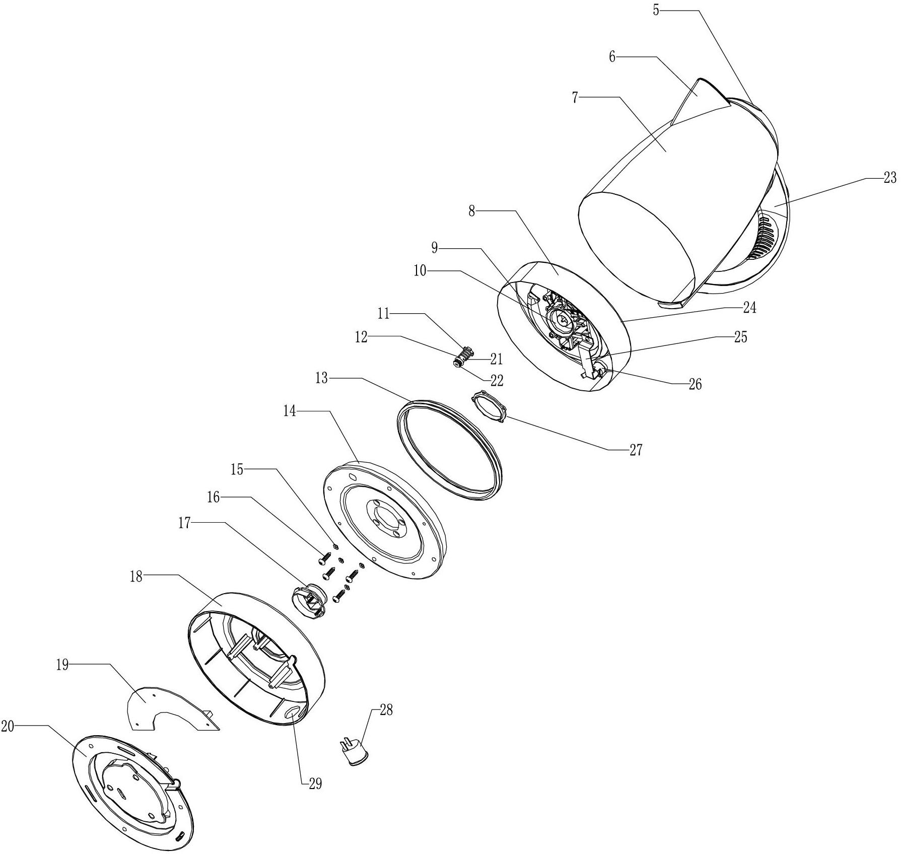
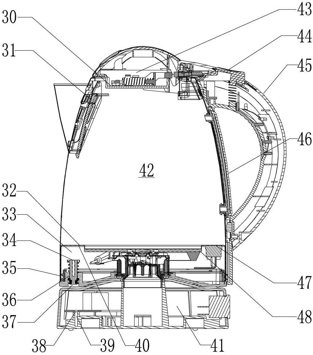
[0026] refer to Figure 1-6 , an electric kettle, comprising a body 2 provided with an upper coupler 10, a base assembly 3 provided with a lower coupler, a control circuit 53 and a user operating device provided in the base assembly 3, the body 2 and The base assembly 3 is connected by an upper and a lower coupler and forms a heating circuit 52 between them. The body 2 includes a container 7 forming a liquid holding chamber. An electric heating assembly 8 is arranged at the bottom of the container 7. The upper 1. The lower coupler is provided with a waterproof structure, and the outside of the bottom of the container 7 is sealed with...


PUM


Abstract

The invention discloses an electric kettle. The electric kettle comprises a body which is provided with an upper coupler, a base component which is provided with a lower coupler, a control circuit which is arranged in the base component, and a user operation device, wherein the body and the base component are connected through the upper coupler and the lower coupler, and a heating circuit is formed between the body and the base component; the body comprises a container which forms a liquid accommodation cavity; the bottom of the container is provided with an electric heating component; waterproof structures are arranged on the upper coupler and the lower coupler; the outer side of the bottom of the container is hermetically provided with a bottom cover; the upper coupler is connected to the bottom cover, and the joint of the upper coupler and the bottom cover is sealed so that a closed cavity is formed between the bottom of the container and the bottom cover; a pressure relief valve device is hermetically arranged on the bottom cover; a bimetallic strip temperature controller is arranged on the lower surface of a bottom wall of the container; and the bimetallic strip temperature controller and the electric heating component are connected in series in the heating circuit.

Description

technical field [0001] The invention relates to a small household appliance, in particular to a household electric kettle. Background technique [0002] Consumers are very familiar with electric kettles, and technicians in the field of electric kettle industry are also very familiar with the structure of electric kettles. Most ordinary electric kettles control the power off of electric kettles through the steam generated after boiling water in electric kettles. The use of steam to control the power off of the electric kettle is defective; the first defect is that the steam generated by the electric kettle equipped with a steam conduit enters the steam conduit after the boiling water is boiled, and the steam in the steam pipe will form condensed water after cooling, and this Condensed water will flow to the electric control part at the bottom. Such a structure is actually a safety hazard. The second defect is that at higher altitudes, even if the water boils, it will not reac...

Claims


Application Information

Patent Timeline
Patent Type & Authority Applications(China)
IPC IPC(8): A47J27/21A47J36/00A47J36/24A47J36/32G05B19/042G05D23/08
Inventor 左祥贵张叶兰黄理水
Owner ZHEJIANG SHAOXING SUPOR DOMESTIC ELECTRICAL APPLIANCE CO LTD
Why Eureka
Try Eureka