Blocking extrusion forming die

A technology of forming molds and occlusive extrusion, applied in the field of metal pressure processing, to achieve the effects of good versatility, good economic benefits, and reduced manufacturing costs

Inactive Publication Date: 2012-09-12
ANHUI UNIVERSITY OF TECHNOLOGY
6 Cites 15 Cited by

AI-Extracted Technical Summary

Problems solved by technology

[0006] The present invention aims at the technical problems existing in the existing occluded extrusion molding dies, and provides...

Abstract

The invention discloses a blocking extrusion forming die, belonging to the field of metal pressure processing technology. The die mainly consists of three parts: a rigid die frame, a floating forming die core and a die locking device, wherein the die frame provides support, fixing and guide effects to the die core; and upper and lower floating concave die modules are automatically locked under the effect of a locking hook device to form a closed cavity. When an upper die holder moves downward, the upper and lower punches move bidirectionally to extrude the bar stock to realize blocking formation of the part. The blocking extrusion forming die provided by the invention easily realizes blocking formation, reduces the requirement for the tonnage of equipment, improves the material forming performance and material utilization rate, and lowers the manufacturing cost.

Application Domain

Technology Topic

Image

  • Blocking extrusion forming die
  • Blocking extrusion forming die

Examples

  • Experimental program(1)

Example Embodiment

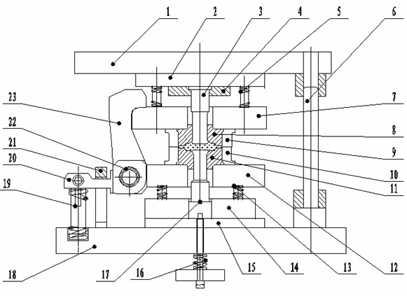
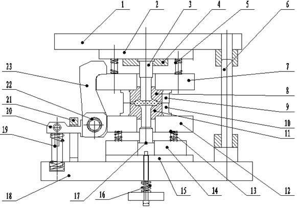
[0013] Attached below figure 1 The present invention is further described.
[0014] Upper punch 3 and lower punch 17 are fixed on upper die base 1 and lower die base 18 with screws and pins by upper fixing plate 4, lower punch guide limit plate 14 and backing plate 15. The upper floating mold base 7 and the lower floating mold base 12 are respectively supported by the upper floating formwork elastic element 5 and the lower floating formwork elastic element 13, and are guided by the inner guide column. Upper die core 8, lower die core 11 are installed on upper floating die base 7, lower floating die base 12 by upper die core cover 9, lower die core cover 10, fixed by pressing plate. The swing bar lock hook 23 is symmetrically installed on the lower floating mold base 12 through a living hinge, and realizes swinging and mold locking by the action of the lock hook support spring 19 during the up and down movement of the floating mold base. In the mold-locked state, a closed mold cavity is formed, and at the same time, the eccentric sleeve 22 is rotated at a certain angle to adjust the mold-clamping gap and improve the mold clamping force of the die. When the upper and lower punches move towards each other, the closed radial extrusion is realized. The upper fixing plate 4 and the lower punch guide limiting plate 14 simultaneously act as a mold limiter to control the degree of deformation of the workpiece. The limit baffle plate 21 limits the upward position of the lock hook of the swing rod, and the lock hook 23 of the swing rod is forced to rotate by the pressing plate 20, and the upper and lower dies are opened to realize automatic separation and separation. The lower punch 17 goes up under the action of the lower jacking device 16 to complete the demoulding process of the workpiece, and finally the workpiece is taken out from the mold core by the reclaiming device.

PUM

no PUM

Description & Claims & Application Information

We can also present the details of the Description, Claims and Application information to help users get a comprehensive understanding of the technical details of the patent, such as background art, summary of invention, brief description of drawings, description of embodiments, and other original content. On the other hand, users can also determine the specific scope of protection of the technology through the list of claims; as well as understand the changes in the life cycle of the technology with the presentation of the patent timeline. Login to view more.

Similar technology patents

A Coherent Target Decomposition Method Based on Scattering Matrix

ActiveCN102262223AGood versatilityImprove accuracyRadio wave reradiation/reflectionScatter matrixPolarimetric sar
Owner:CENT FOR EARTH OBSERVATION & DIGITAL EARTH CHINESE ACADEMY OF SCI

Classification and recommendation of technical efficacy words

  • Easy to repair and replace
  • Good versatility

Non-inflation low-speed cross-country vehicle tire

PendingCN106915203AEasy to repair and replaceAvoid damageNon-inflatable tyresOff-road vehicle tyresAir springLow speed
Owner:SHANDONG JIANZHU UNIV +1

Image recognition method and system

Owner:新方正控股发展有限责任公司 +1

Method and device for processing image

Owner:GLOBAL INNOVATION AGGREGATORS LLC
Why Eureka
Try Eureka